Coupling structure dielectric resonator filter

A dielectric resonator and coupling structure technology, applied in the microwave field, can solve the problems of increased size and processing difficulty, complexity, and large filter structure size, and achieve the effects of miniaturization, increased transmission zero point, and improved out-of-band suppression

Active Publication Date: 2018-08-10
XIDIAN UNIV
View PDF1 Cites 5 Cited by
  • Summary
  • Abstract
  • Description
  • Claims
  • Application Information

AI Technical Summary

Problems solved by technology

However, since the traditional dielectric filter with cross-coupling structure is more complex and still increases the size and processing difficulty, the dielectric resonator filter with cross-coupling linear structure has begun to receive widespread attention.
[0003] For example, in 2012, Simone Bastioli et al. published "InlinePseudoelliptic TE 01δ -Mode Dielectric Resonator Filters Using MultipleEvanescent Modes to Selectively Bypass Orthogonal Resonators", proposed a three-cylinder dielectric resonator orthogonally placed in a rectangular waveguide structure, using a ring feeder structure to achieve external coupling, by loading the inclined waveguide edge A 45° metal rod or an asymmetric metal diaphragm produces coupling between two orthogonal evanescent modes, thereby realizing coupling between adjacent orthogonal dielectric resonators, forming a cross-coupling structure between cascaded three-stage resonators , to achieve the purpose of designing a quasi-elliptic function filter. However, due to the introduction of metal rods and asymmetric metal diaphragms, the size of the filter structure will inevitably be too large, and the miniaturization of the filter cannot be realized.

Method used


Image

  • Coupling structure dielectric resonator filter
  • Coupling structure dielectric resonator filter
  • Coupling structure dielectric resonator filter

Examples


Embodiment 1

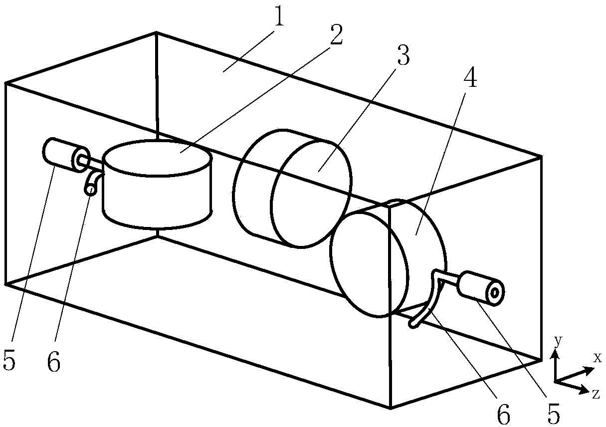
[0025] refer to figure 1 , the present invention includes a rectangular waveguide 1 with both ends closed, and a first dielectric resonator 2, a second dielectric resonator 3, a third dielectric resonator 4 fixed in sequence in the cavity of the rectangular waveguide 1, and two dielectric resonators fixed in the rectangular waveguide 1. Terminal radio frequency connector 5 and the loop feeder 6 connected on the radio frequency connector 5;

[0026] The rectangular waveguide 1 adopts a square waveguide with a detachable top cover, the side length of the square is a, a=31.6, and through holes are punched at both ends to facilitate the assembly of the radio frequency connector 5;

[0027] The first dielectric resonator 2, the second dielectric resonator 3 and the third dielectric resonator 4 adopt the same cylindrical structure, and all work on the TE 01δ mode, and fixed in the rectangular waveguide 1 with a foam with a relative permittivity of 1, with a thickness of H=8 and a r...

Embodiment 2

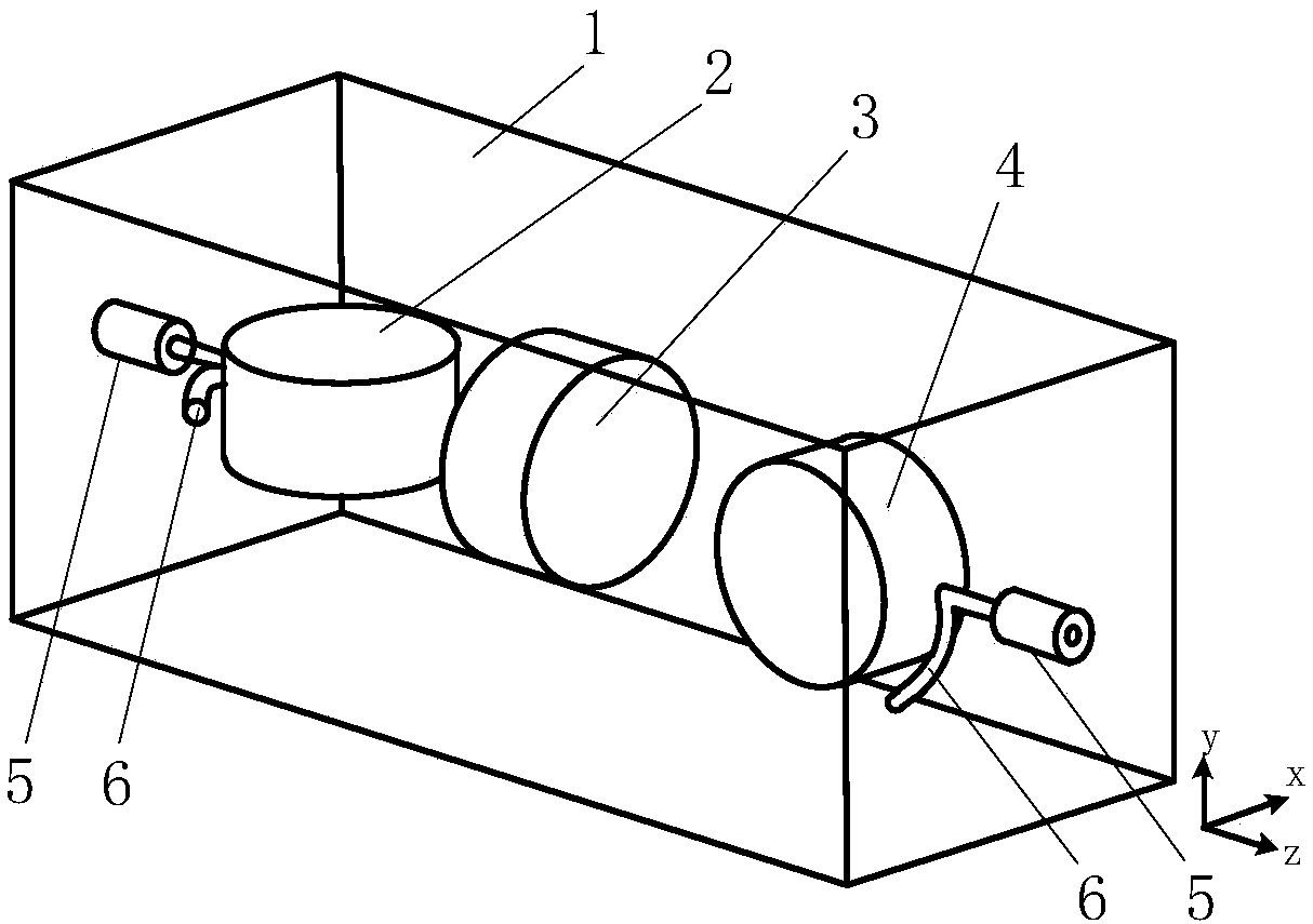
[0036] refer to figure 2 , the present invention includes a rectangular waveguide 1 with both ends closed, and a first dielectric resonator 2 fixed in the cavity of the rectangular waveguide 1, a third dielectric resonator 4, and a radio frequency connector 5 fixed at both ends of the rectangular waveguide 1 and connected to the Loop feeder 6 on the radio frequency connector 5;

[0037] The rectangular waveguide 1 with both ends closed, and the first dielectric resonator 2, the second dielectric resonator 3, the third dielectric resonator 4 fixed in sequence in the cavity of the rectangular waveguide 1, and the radio frequency The connector 5 and the loop feeder 6 connected to the radio frequency connector 5 are the same as in Embodiment 1;

[0038] The difference from Embodiment 1 is that the second dielectric resonator 3 is offset from the axis of the transmission direction of the rectangular waveguide 1, and the offset point is located on the bisector of the angle between...

Embodiment 3

[0041] The present invention includes a rectangular waveguide 1 with both ends closed, and a first dielectric resonator 2 fixed in the cavity of the rectangular waveguide 1, a third dielectric resonator 4, and a radio frequency joint 5 fixed at both ends of the rectangular waveguide 1 and connected to a radio frequency Loop feeder 6 on connector 5;

[0042] The rectangular waveguide 1 with both ends closed, and the first dielectric resonator 2, the second dielectric resonator 3, the third dielectric resonator 4 fixed in sequence in the cavity of the rectangular waveguide 1, and the radio frequency The connector 5 and the loop feeder 6 connected to the radio frequency connector 5 are the same as in Embodiment 1;

[0043] The difference from Embodiment 1 is that the second dielectric resonator 3 is offset from the axis of the transmission direction of the rectangular waveguide 1, and the offset point is located on the bisector of the angle between the x-axis and the y-axis in th...


PUM


Abstract

The present invention provides a coupling structure dielectric resonator filter. The coupling structure dielectric resonator filter can solve the problem of the conventional dielectric resonator filter, for example, the conventional dielectric resonator filter can not realize structural miniaturization and improve pass-band selectivity at the same time. The coupling structure dielectric resonatorfilter comprises a rectangular waveguide external cavity, a first dielectric resonator arranged along the Y axis direction, a second dielectric resonator arranged along the Z axis direction, a third dielectric resonator arranged along the X axis direction, annular feeder lines and radio frequency connectors. The three dielectric resonators are centrally symmetric, and the structure sizes of the three dielectric resonators are the same. The geometric centers of the first dielectric resonator and the third dielectric resonator are located at the axis of the transmission direction of the rectangular waveguide, the geometric center of the second dielectric resonator deviates from the axis of the transmission direction of the rectangular waveguide, and the deviation point is located at the angular bisector of the X axis and the Y axis. By regulating the value of the deviation amount and the deviation direction, the sizes of direct coupling and cross coupling between the resonators can be controlled, so that the purposes of controlling the bandwidth of the filter and the position of the transmission zero point are realized, and the miniaturization of the filter structure is realized.

Description

technical field [0001] The invention belongs to the field of microwave technology, and relates to a dielectric resonator filter, in particular to a coupling structure dielectric resonator filter, which can be used for a radio frequency front end of a wireless communication system. Background technique [0002] With the rapid development of wireless communication, spectrum resources become very tight, so higher requirements are placed on the performance of microwave filters. Microwave filters with characteristics such as high selectivity, low insertion loss, high power capacity, light weight, and good thermal stability have begun to receive widespread attention. The dielectric resonator selects ceramic dielectric materials with high dielectric constant, high quality factor and high thermal stability coefficient, and uses TE 01δ modulo or higher order HE 11 Mode and other resonant modes are widely used in the design of microwave filters. At the same time, because the dimens...

Claims


Application Information

Patent Timeline
Patent Type & Authority Applications(China)
IPC IPC(8): H01P1/208
CPCH01P1/2084
Inventor 吴边夏磊樊炽王跃霖陈建忠
Owner XIDIAN UNIV
Why Eureka
Try Eureka