Reactor parallel air cooling heat-removal system
A heat dissipation system and reactor technology, applied in the cooling/ventilation of substation/switchgear, electrical components, substation/power distribution device shell, etc., can solve the problems of low reliability, high cost of reactor, heavy weight of reactor, etc. , to achieve the effect of convenient installation and maintenance, high protection level and efficient heat dissipation
- Summary
- Abstract
- Description
- Claims
- Application Information
AI Technical Summary
Problems solved by technology
Method used
Image

Examples
Embodiment 1
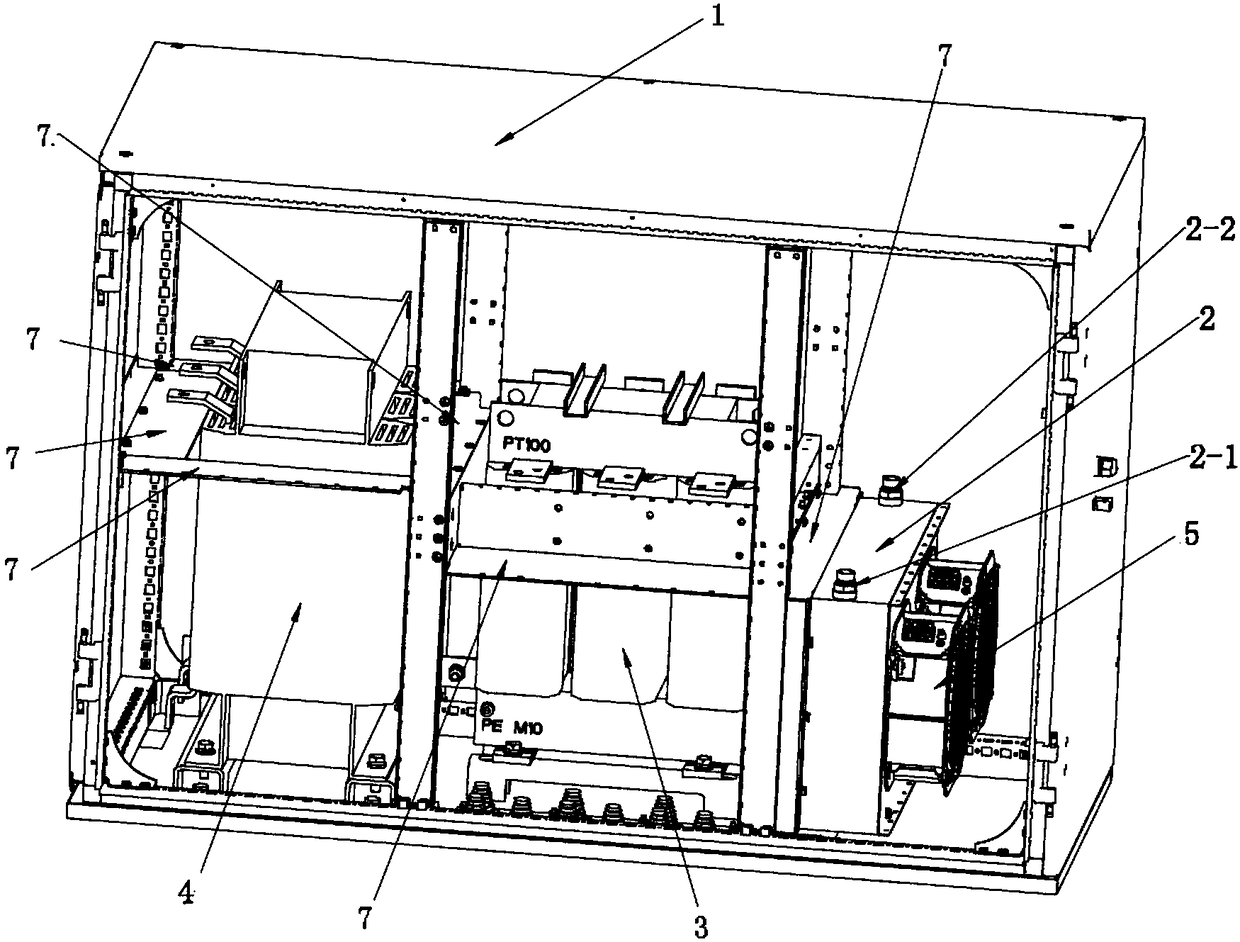
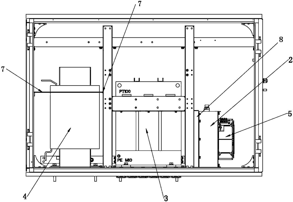
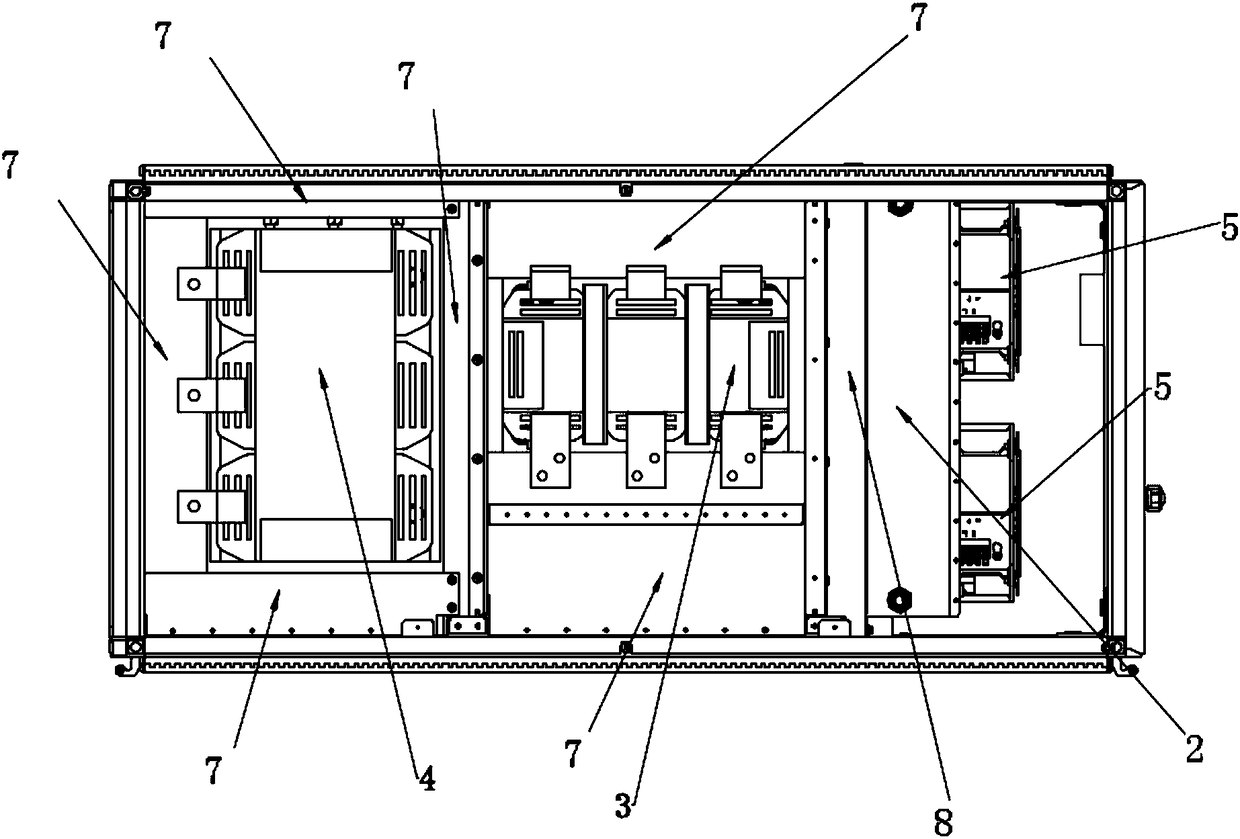
[0021] A reactor parallel air-cooled heat dissipation system, such as Figure 1~4 As shown, including the cabinet 1, the cabinet 1 is equipped with an organic side reactor 3 and a grid side reactor 4, and the generator side reactor 3 and the grid side reactor 4 are adjacent to and arranged in parallel at the bottom of the cabinet 1; it also includes a fan 5 and the water-air heat exchanger 2; the water-air heat exchanger 2 is arranged on the side close to the machine-side reactor 3, and an air cavity 6 is arranged between the water-air heat exchanger 2 and the machine-side reactor 3; the fan 5 is fixed On the water-wind heat exchanger 3, and the air outlet of the fan 5 is facing the air inlet of the water-wind heat exchanger; a wind cavity 8 is formed between the air outlet of the fan 5 and the air inlet of the water-wind heat exchanger 2; The sides of the side reactor 3 and the grid side reactor 4 and the side of the cabinet 1 are provided with several windshields 7 to preven...
PUM
 Abstract
Description
Claims
Application Information
PatSnap Eureka turns technology decisions into work you can execute. Powered by our Innovation Knowledge Graph, it runs expert workflows across engineering, life sciences, materials and intellectual property. Get your review-ready output in minutes.


