Textile displaying equipment

A technology for displaying equipment and textiles, applied in display stands, display hangers, display shelves, etc., can solve the problems of textile dust accumulation and inconvenience in taking textiles, and achieve good fixing effect

Active Publication Date: 2018-08-14
江苏天绚家居科技有限公司
View PDF12 Cites 4 Cited by
  • Summary
  • Abstract
  • Description
  • Claims
  • Application Information

AI Technical Summary

Problems solved by technology

[0005] The present invention overcomes the disadvantages that the existing textile display racks are mostly open-air when displaying textiles, which easily accumulates dust on textiles, and the display rods of the display

Method used


Image

  • Textile displaying equipment
  • Textile displaying equipment
  • Textile displaying equipment

Examples


Embodiment 1

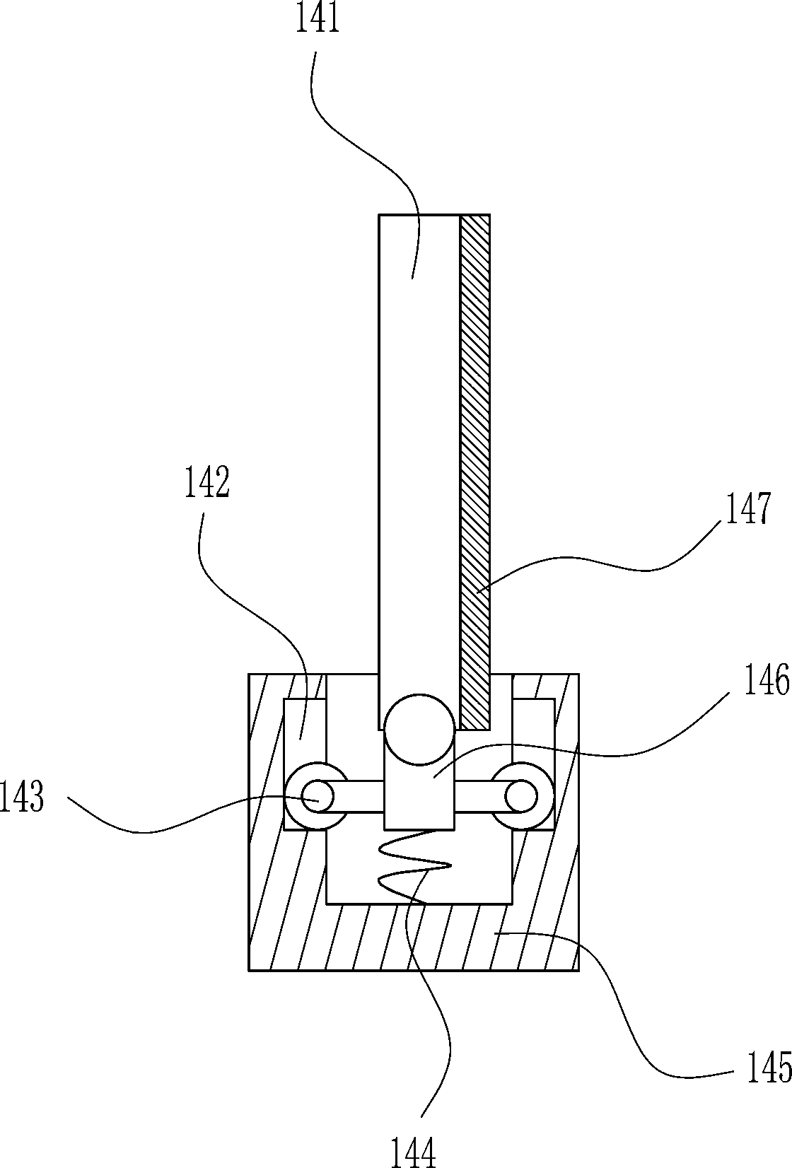
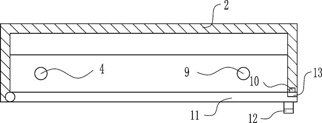
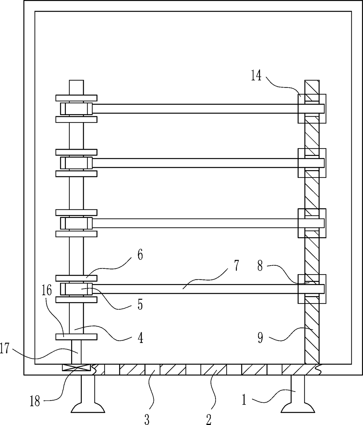
[0030] A textile display device such as Figure 1-8 As shown, it includes a pillar 1, a box body 2, a first pole 4, a swivel ring 5, a limit plate 6, a placement pole 7, a second pole 9, a first magnet block 10, a glass door 11, and a pull ring 12 With the second magnet block 13, the bottom of the box body 2 is symmetrically arranged with pillars 1, the bottom wall of the box body 2 is evenly provided with small holes 3, and the left side of the box body 2 is rotated to be provided with a glass door 11, and the right part of the glass door 11 A draw ring 12 is provided in the front, a second magnet block 13 is provided on the right rear side of the glass door 11, and a first magnet block 10 is provided at the front of the right wall of the casing 2, and the first magnet block 10 cooperates with the second magnet block 13. A first pole 4 and a second pole 9 are arranged on the front side of the inner bottom of the box body 2, the second pole 9 is located on the right side of th...

Embodiment 2

[0032] A textile display device such as Figure 1-8 As shown, it includes a pillar 1, a box body 2, a first pole 4, a swivel ring 5, a limit plate 6, a placement pole 7, a second pole 9, a first magnet block 10, a glass door 11, and a pull ring 12 With the second magnet block 13, the bottom of the box body 2 is symmetrically arranged with pillars 1, the bottom wall of the box body 2 is evenly provided with small holes 3, and the left side of the box body 2 is rotated to be provided with a glass door 11, and the right part of the glass door 11 A draw ring 12 is provided in the front, a second magnet block 13 is provided on the right rear side of the glass door 11, and a first magnet block 10 is provided at the front of the right wall of the casing 2, and the first magnet block 10 cooperates with the second magnet block 13. A first pole 4 and a second pole 9 are arranged on the front side of the inner bottom of the box body 2, the second pole 9 is located on the right side of th...

Embodiment 3

[0035] A textile display device such as Figure 1-8 As shown, it includes a pillar 1, a box body 2, a first pole 4, a swivel ring 5, a limit plate 6, a placement pole 7, a second pole 9, a first magnet block 10, a glass door 11, and a pull ring 12 With the second magnet block 13, the bottom of the box body 2 is symmetrically arranged with pillars 1, the bottom wall of the box body 2 is evenly provided with small holes 3, and the left side of the box body 2 is rotated to be provided with a glass door 11, and the right part of the glass door 11 A draw ring 12 is provided in the front, a second magnet block 13 is provided on the right rear side of the glass door 11, and a first magnet block 10 is provided at the front of the right wall of the casing 2, and the first magnet block 10 cooperates with the second magnet block 13. A first pole 4 and a second pole 9 are arranged on the front side of the inner bottom of the box body 2, the second pole 9 is located on the right side of th...


PUM


Abstract

The invention relates to displaying equipment, in particular to textile displaying equipment. The textile displaying equipment is closed, the amount of dropping dust can be reduced, and textile is taken conveniently. The textile displaying equipment comprises supporting columns, a box, a first strut, a rotating ring, a limiting plate, a placement rod and the like; the supporting columns are symmetrically arranged on the bottom of the box in the left-right direction; small holes are uniformly formed in the bottom wall of the box; a glass door is rotatably arranged on the left side of the frontof the box; a pull ring is arranged at the front of the right of the glass door; a second magnet is arranged on the rear side of the right of the glass door; and a first magnet is arranged at the front of the right wall of the box. The textile displaying equipment is closed, the amount of dropping dust can be reduced, the textile is taken conveniently, by the textile displaying equipment, the textile is closed in the box, people watch the textile through the glass door, the displaying effect is achieved, moreover, the amount of dropping dust can be reduced in the box, and by cooperation of theplacement rod, a first groove and the rotating ring, the textile is taken conveniently.

Description

technical field [0001] The invention relates to a display device, in particular to a textile display device. Background technique [0002] Textiles are products that are spun. Textile is the general term for spinning and weaving. Ancient Chinese textile and printing and dyeing technology has a very long history. As early as in the primitive society, in order to adapt to climate change, the ancients knew how to use local materials and use natural resources as the basis for textile, printing and dyeing. Raw materials, as well as the manufacture of simple textile tools, until today, our daily clothes, some daily necessities and artworks are all products of textile and printing and dyeing technology. [0003] After the design and production of textiles, textiles will be displayed. However, when the existing textile display racks display textiles, most of the textile display racks are open-air, which is easy for textiles to accumulate dust, and the display poles of the display r...

Claims


Application Information

Patent Timeline
IPC IPC(8): A47F7/16A47F3/00A47F5/00
CPCA47F3/005A47F5/0006A47F7/166
Inventor 林娟
Owner 江苏天绚家居科技有限公司
Why Eureka
Try Eureka