Pre-torsion moment application device of torsion rod spring for new energy automobile
A technology of new energy vehicles and torsion bar springs, which is applied to vehicle parts, transportation and packaging, etc., can solve problems such as the unexplained torsion bar spring pre-torsion process, and achieve the effect of improving versatility
- Summary
- Abstract
- Description
- Claims
- Application Information
AI Technical Summary
Problems solved by technology
Method used
Image

Examples
Embodiment 1
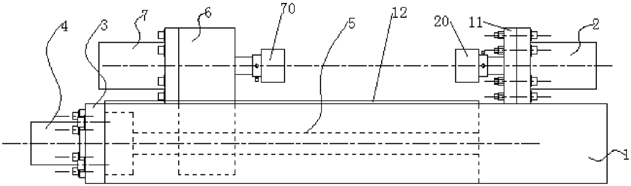
[0041] The new energy vehicle uses a torsion bar spring pre-torsion moment applying device. After the torsion bar spring is quenched and tempered, insert one end of the torsion bar spring into the end sleeve 120 at the end of the output shaft of the stepping motor 2, and then Clamp the torsion bar spring close to the horizontal position, then start the servo motor 4, the servo motor 4 works, drives the screw rod 5 to rotate, and makes the slider 6 move along the rectangular groove 10 to the side of the stepping motor 1 2 until the end sleeve The second 70 is inserted into the other side of the torsion bar spring, and then the servo motor 4 is stopped to work. At this time, the torsion bar spring is clamped, and then the stepping motor one 2 and the stepping motor two 7 are started simultaneously, because the stepping motor one 2 and stepping motor two 7 have the same stepping angle, and the stepping motor one 2 and stepping motor two 7 turn in opposite directions to realize the...
Embodiment 2
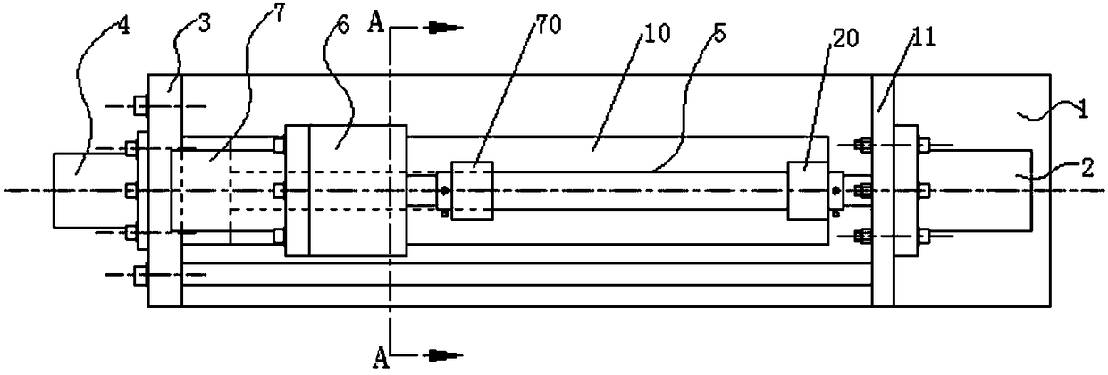
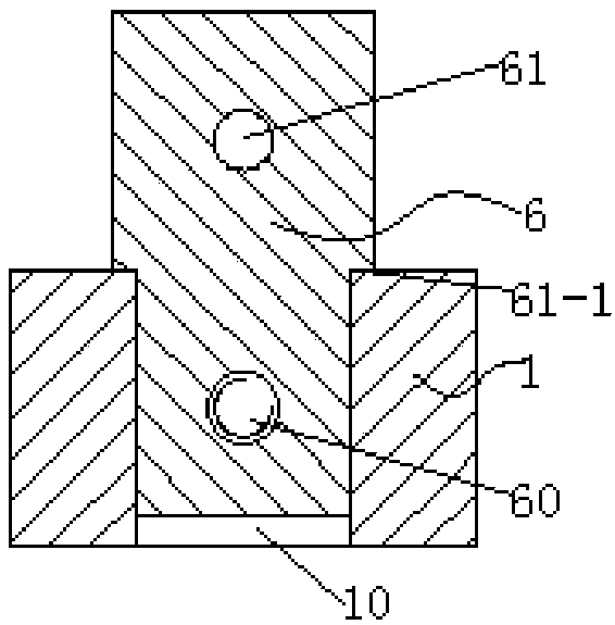
[0043] On the basis of Embodiment 1, the following improvements are made: because the servo motor 4 is connected to the bearing end seat 3 by bolts, the output shaft of the servo motor 4 is coaxially connected to one end of the screw rod 5, and the other end of the screw rod 5 One end is connected with the base 1 through a rolling bearing, the slider 6 is slidingly connected with the rectangular groove 10, the lower end of the slider 6 is provided with a threaded hole 60, and the screw mandrel 5 and the threaded hole 60 form a spiral pair connection, the slider 6 The upper end is provided with a cylindrical hole 61, and the stepper motor 2 7 is connected to the slider 6 by bolts, and the output shaft of the stepper motor 2 7 passes through the cylindrical hole 61, so the servo motor 4 can drive the slider 6 along the rectangular groove. 10 movement, changing the distance between end sleeve one 20 and end sleeve two 70, realizing the operation of applying pre-torsion torque to t...
Embodiment 3
[0045] On the basis of Example 1, the following improvements are made: the upper end surface of the base 1 is polished, the slider 6 is a "T"-shaped structure, and both sides of the slider 6 are provided with convex edges 61- 1, and the lower end surface of the convex edge 61-1 has been polished and is in contact with the upper end surface of the base 1, which ensures the stability of the sliding block 6 driven by the screw rod 5 along the rectangular groove 10, thereby ensuring the stability of the end sleeve 120 The coaxiality of the central axis and the central axis of the end sleeve 2 70 ensures the levelness of the torsion bar spring. A scale 12 is provided on the upper end surface of the base 1, and the scale 12 is a steel ruler, which realizes the visual adjustment of the distance between the end sleeve 1 of 20 and the end sleeve 2 of 70. The connecting plate 11 can be welded on the right end face of the base 1, or can be connected by bolts to ensure the stability of th...
PUM
 Abstract
Description
Claims
Application Information
 - R&D
- Intellectual Property
- Life Sciences
- Materials
- Tech Scout
- Unparalleled Data Quality
- Higher Quality Content
- 60% Fewer Hallucinations
Browse by: Latest US Patents, China's latest patents, Technical Efficacy Thesaurus, Application Domain, Technology Topic, Popular Technical Reports.
© 2025 PatSnap. All rights reserved.Legal|Privacy policy|Modern Slavery Act Transparency Statement|Sitemap|About US| Contact US: help@patsnap.com