Eureka AIR delivers breakthrough ideas for toughest innovation challenges, trusted by R&D personnel around the world.

An Optimum Method for Up-and-Up Milling of Carbon Fiber Composite Materials

A composite material and carbon fiber technology, applied in metal processing equipment, cutting tools for milling machines, workpieces, etc., can solve the problem of low surface roughness and delamination damage, without in-depth analysis of the essential influence of milling methods on processing quality, and has not yet formed an optimal solution Principles and methods, etc., to achieve high-precision milling, good engineering application prospects, and simple calculation steps

Active Publication Date: 2019-04-23
DALIAN UNIV OF TECH
View PDF5 Cites 0 Cited by
  • Summary
  • Abstract
  • Description
  • Claims
  • Application Information

AI Technical Summary

Problems solved by technology

At present, research on the selection of milling methods for carbon fiber composite materials is mostly limited to qualitatively describing the impact of milling methods on processing quality, and no specific optimization principles and methods have been formed.
For example: Prashanth Janardhan et al. conducted a comparative analysis of the effects of forward milling and up milling on the milling quality of carbon fiber composite materials in the article "Edge Trimming of CFRP with Diamond Interlocking Tools". Climb milling, that is, the surface roughness and delamination damage are both low, but this study did not deeply analyze the essential impact of milling methods on processing quality

Method used

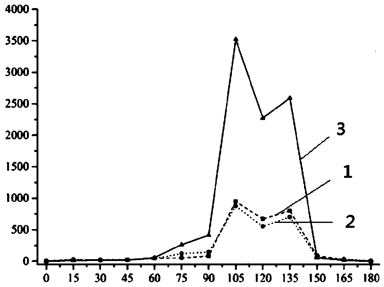
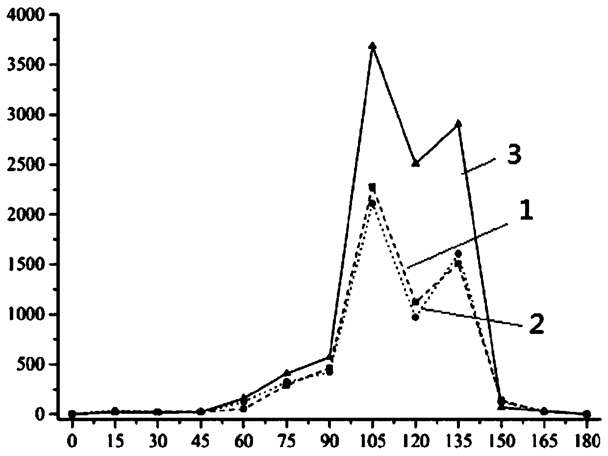
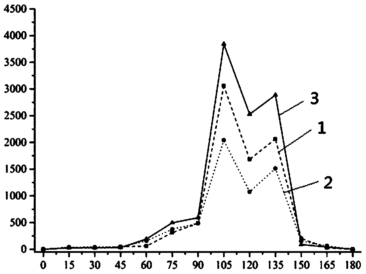

Image

  • An Optimum Method for Up-and-Up Milling of Carbon Fiber Composite Materials
  • An Optimum Method for Up-and-Up Milling of Carbon Fiber Composite Materials
  • An Optimum Method for Up-and-Up Milling of Carbon Fiber Composite Materials

Examples


Embodiment Construction

[0028] The specific implementation of the present invention will be described in detail below in conjunction with the drawings and technical solutions.

[0029] In this embodiment, a cemented carbide double straight-edged milling cutter with a rake angle of 5°, a back angle of 10°, and a blunt radius of 15 μm is used to mill a T800 grade carbon fiber composite unidirectional plate with a fiber angle of 150° Preferably, the processing parameters are shown in Table 1:

[0030] Table 1 Milling processing parameters

[0031]

[0032] The first step: Solve the actual range of fiber cutting angle during the up and down milling process respectively

[0033] From the processing parameters in Table 1, we get:

[0034]

[0035] Satisfy: The actual range of fiber cutting angle in up-milling processing is:

[0036]

[0037] The corresponding range of fiber cutting angle in down milling is:

[0038] ψ D =180°-ψ U ∈[30°,66.87°]

[0039] Step 2: Determine the optimal range of fiber cutting angle accord...


PUM

PropertyMeasurementUnit
radiusaaaaaaaaaa

Abstract

The invention relates to an optimizing selection method of carbon fiber composite down milling and up milling machining manners and belongs to the technical field of machining. According to the optimizing selection method of the carbon fiber composite down milling and up milling machining manners, based on milling machining parameters, the actual change ranges of the fiber cutting angles in the milling process are correspondingly worked out, according to the properties of a utilized material and the utilized cutter structure, in an experiment or finite element calculation manner, the fiber cutting angle range enabling the machining quality to be the best is determined, the proportions of the condition that the actual ranges of the fiber cutting angles during down milling and up milling arewithin the optimal range are calculated finally, and the milling manner with the larger proportion is selected as the optimal milling manner under the working condition. By the adoption of the optimizing selection method, a new method can be provided for achievement of high-quality high-efficiency high-precision milling of a carbon fiber composite component, optimizing selection of the milling manners is achieved, the calculation steps are simple and convenient, and the optimizing selection method has good engineering application prospect.

Description

Technical field [0001] The invention belongs to the field of mechanical processing, and relates to a preferred method for up and down milling of carbon fiber composite materials. Background technique [0002] Compared with traditional metal materials, carbon fiber composite materials have the advantages of high specific strength, high specific modulus, and overall design. They are widely used in large-scale load-bearing components of advanced equipment in the aerospace field. These large load-bearing components are usually integrally formed by laying and curing, so as to realize the integrated design and manufacture of structure and performance, which effectively improves the flexibility of performance design. However, in the link of assembly and connection, most of these components need to be milled to remove excess materials to make their shape and position accuracy meet tolerance requirements. In this process, due to the anisotropy and heterogeneity of carbon fiber composite ...

Claims


Application Information

Patent Timeline
Patent Type & Authority Patents(China)
IPC IPC(8): B23C3/00
CPCB23C3/00B23C2226/27
Inventor 王福吉张博宇王东胡海波贾振元
Owner DALIAN UNIV OF TECH
Why Eureka
Eureka Blog
Learn More