H steel welding process

A welding process and steel plate technology, applied in welding equipment, welding equipment, auxiliary welding equipment, etc., can solve the problems of low production efficiency, deviation of welding seam, unable to meet the parallelism of H steel, etc., so as to improve work efficiency and reduce workload. Effect

Inactive Publication Date: 2018-08-14
关吉举
View PDF6 Cites 2 Cited by
  • Summary
  • Abstract
  • Description
  • Claims
  • Application Information

AI Technical Summary

Problems solved by technology

However, due to people holding on for a long time, the steel plates will definitely move, so that the weld seam will deviate greatly from the predetermined position, and even bend. Since the H steel is several meters long, the deformed products cannot be used at all, and cannot meet the requirements. The parallelism of the H steel and the verticality requirements between the middle vertical plate and the upper and lower steel plates can only be scrapped
In addition, due to the long weld seam, the temperature of the first welding place is high, and the temperature of the second welding place is low. The temperature of the two sides of the steel plate to be welded is different, which will cause a slight displacement or even distortion of the weld seam to be welded. Twisted or bent vertically up or down
Greatly affects product quality, and production efficiency is also very low
[0003] An existing solution, for example, the patent No. CN 103317278 B is a patent that connects the vertical plate and the upper plate or the lower plate through a plurality of diagonal bracing blocks to fix them, and the two ends of the diagonal bracing blocks are connected to the vertical The plate, upper plate, and lower plate are welded. This method requires multiple welds, and the diagonal brace needs to be removed later, so the work is cumbersome and the efficiency is low.

Method used


Image

  • H steel welding process
  • H steel welding process

Examples


Embodiment 1

[0024] A kind of H steel welding process is characterized in that comprising the following steps:

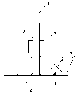
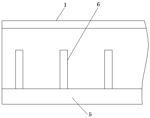
[0025] a) Prepare three rectangular steel plates, namely the upper plate, the lower plate and the vertical plate. The vertical plate is a steel plate welded vertically between the upper plate and the lower plate. The upper side is placed vertically along a straight line;

[0026] b) Install fixing clips on both sides of the vertical plate to fix the vertical plate. The fixed clip includes a U-shaped base and an inclined splint. The inclined splint is installed on the U-shaped base, and the U-shaped base is installed on the lower plate. The two ends of the plate are welded to the two ends of the U-shaped base, and the magnet sheet is installed on the inclined splint, and the magnet sheet is attracted to the side of the vertical plate;

[0027] c) Interval spot welding of the weld to be welded between the lower edge of the vertical plate and the upper side of the lower plate;

...


PUM


Abstract

The invention discloses an H steel welding process. The welding process is characterized by comprising following steps: a, three rectangular steel plates are prepared and comprise an upper plate, a lower plate and a vertical plate, the vertical plate is a steel plate vertically welded between the upper plate and the lower plate, the lower plate is put flatly, and the position, on the lower side edge of the vertical plate, of the upper side face of the lower plate is vertically placed along the straight line; b, fixed clamp bodies are arranged on the two sides of the vertical plate, the vertical plate can be fixed, each fixed clamp body comprises a U-shaped bottom plate and an inclined clamping plate, the inclined clamping plates are mounted on the U-shaped bases, the U-shaped bases are arranged on the lower plate, the two ends of the lower plate are welded with the two ends of the U-shaped base, magnet pieces are arranged on the inclined clamping plates, and the magnet pieces and the side faces of the vertical plate are attracted. The two ends of the U-shaped bases are welded with the two ends of the lower plate or the upper plate, two welding positions exist, workloads are reduced, and work efficiency is improved.

Description

technical field [0001] The invention relates to the technical field of welding, in particular to an H steel welding process. Background technique [0002] H steel is composed of three steel plates, the upper and lower two steel plates are parallel to each other, the middle vertical plate stands vertically between the upper and lower two steel plates, and is perpendicular to the upper and lower two steel plates, and the upper and lower edges of the vertical plate are in contact with the upper and lower two steel plates. Four weld seams to be welded are formed between them. Now when welding H steel, it is generally used to manually support the vertical plate, and manually ensure that the welding seam does not deviate from the predetermined welding seam. However, due to people holding on for a long time, the steel plates will definitely move, so that the weld seam will deviate greatly from the predetermined position, and even bend. Since the H steel is several meters long, the...

Claims


Application Information

Patent Timeline
Patent Type & Authority Applications(China)
IPC IPC(8): B23K31/02B23K37/00B23K37/04
CPCB23K31/022B23K37/00B23K37/0443
Inventor 关吉举
Owner 关吉举
Why Eureka
Try Eureka