Linked swing arm conveying mechanism of distributing conveyor line

A technology of diversion conveying and conveying mechanism, which is applied in the field of warehousing and logistics. It can solve the problems of non-continuous conveying, large space occupation, and low conveying efficiency, and achieve high cargo diversion efficiency, stable operation, and low noise.

Pending Publication Date: 2018-08-14
WUXI GALAXIS AUTOMOTION MANAGEMENT GMBH
View PDF0 Cites 2 Cited by
  • Summary
  • Abstract
  • Description
  • Claims
  • Application Information

AI Technical Summary

Problems solved by technology

At present, in the process of cargo transportation, it often involves the mixed transportation of goods of various specifications, which needs to be automatically diverted according to the type of goods. The conventional processing method is to set up a branch line to divert the goods on the same conveying layer or use an elevator to divert the goods On the conveyor lines to different levels, however, there is a problem of occupying a large space when diverting goods by using bifurcated lines, and there is a problem that the goods cannot be continuously transported by using elevators to divert goods, and its transport efficiency is low. Therefore, it is urgent to solve the problem

Method used


Image

  • Linked swing arm conveying mechanism of distributing conveyor line
  • Linked swing arm conveying mechanism of distributing conveyor line
  • Linked swing arm conveying mechanism of distributing conveyor line

Examples


Embodiment Construction

[0017] The technical solutions of the present invention will be further described below in conjunction with the accompanying drawings and through specific implementation methods. It should be understood that the embodiments described here are only used to explain the present invention, but not to limit the present invention.

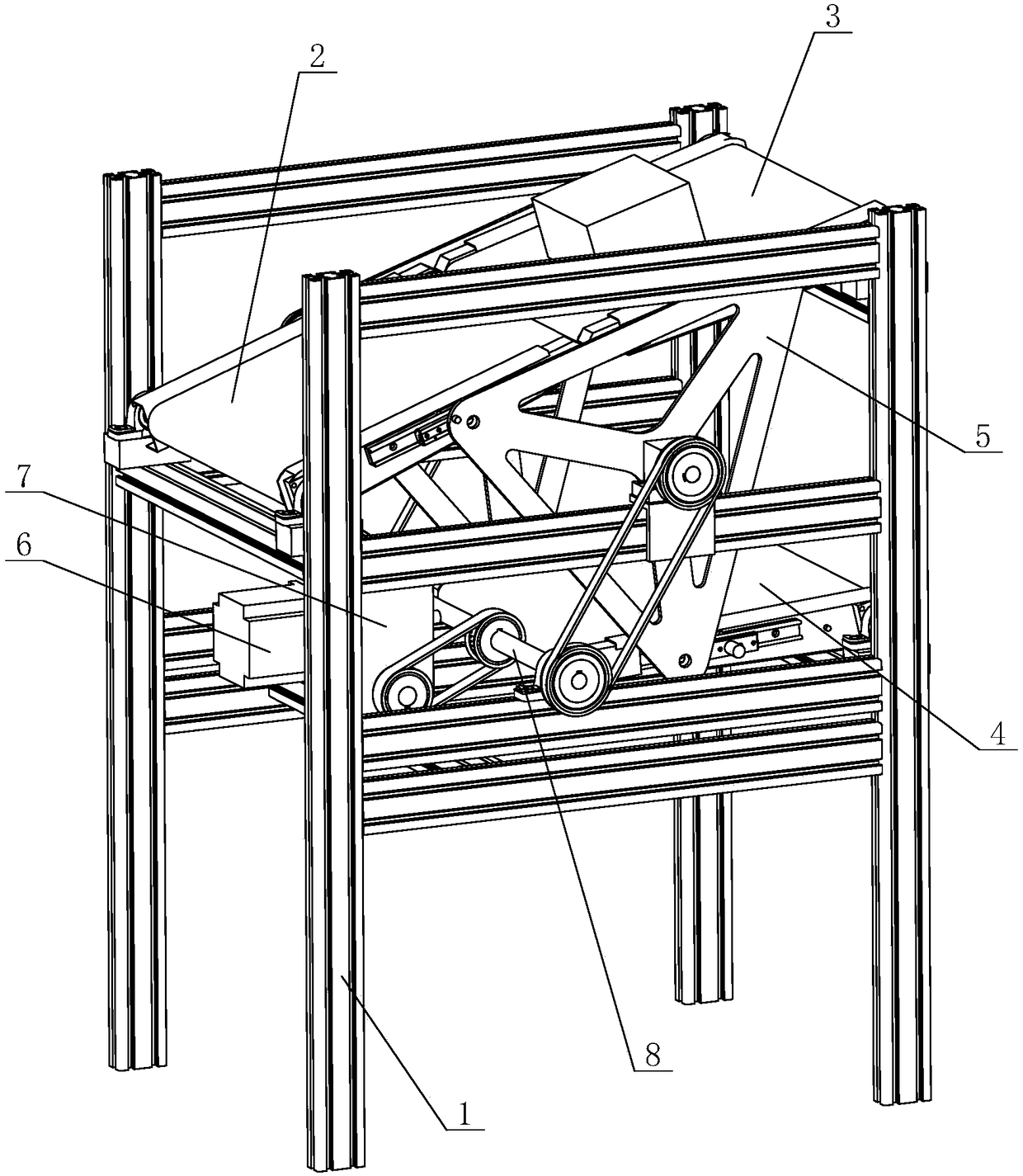
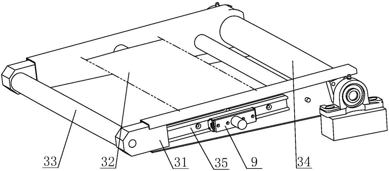
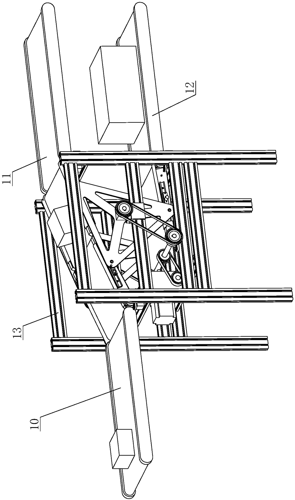
[0018] Please refer to figure 1 and figure 2 As shown, in this embodiment, a linkage swing arm conveying mechanism of a shunt conveying line includes a frame 1, a controller and a swing arm conveying line, and the swing arm conveying line includes a first conveying line 2, a second conveying line line 3, the third conveying line 4, the front end of the first conveying line 2 is hinged on the front end of the frame 1, and both sides of the first conveying line 2 are provided with first slide rails, and the first slide rails are arranged along the The conveying direction of the first conveying line 2 is arranged, the rear end of the second conveying lin...


PUM


Abstract

The invention discloses a linked swing arm conveying mechanism of a distributing conveyor line. The linked swing arm conveying mechanism comprises a rack, a controller and a swing arm conveyor line, wherein the swing arm conveyor line comprises a first conveyor line, a second conveyor line and a third conveyor line; the front end of the first conveyor line is hinged to the front end of the rack; first slide rails are arranged at the two sides of the first conveyor line; the rear end of the second conveyor line is hinged on the upper part of the rear end of the rack; second slide rails are arranged at the two sides of the second conveyor line; the rear end of the third conveyor line is hinged to the lower part of the rear end of the rack; third slide rails are arranged at the two sides of the third conveyor line; a linked bracket can be rotatably connected on the rack; a drive device is arranged on the rack; the linked bracket comprises a bracket body; a first slide block, a second slide block and a third slide block are connected on the bracket body; and the first slide block, the second slide block and the third slide block are distributed in the form of a triangle. The linked swing arm conveying mechanism has the characteristics of being small in space usage, stable and reliable in operation, low in noise and convenient to maintain.

Description

technical field [0001] The invention relates to the field of warehousing and logistics, in particular to a linkage swing arm conveying mechanism of a distribution conveying line. Background technique [0002] Warehouse logistics refers to the use of self-built or leased warehouses and venues to store, store, load, unload, and distribute goods. [0003] Conveyor line is one of the important equipment of warehousing logistics. At present, in the process of cargo transportation, it often involves the mixed transportation of goods of various specifications, which needs to be automatically diverted according to the type of goods. The conventional processing method is to set up a branch line to divert the goods on the same conveying layer or use an elevator to divert the goods On the conveyor lines to different levels, however, there is a problem of occupying a large space when diverting goods by using bifurcated lines, and there is a problem that the goods cannot be continuously...

Claims


Application Information

Patent Timeline
Patent Type & Authority Applications(China)
IPC IPC(8): B65G1/04B65G47/52B65G23/04B65G23/06B65G43/08
CPCB65G1/04B65G23/04B65G23/06B65G43/08B65G47/52B65G2203/044
Inventor 沈鹭谷春光杨艳
Owner WUXI GALAXIS AUTOMOTION MANAGEMENT GMBH
Why Eureka
Try Eureka