Fabricated toilet convenient to mount and mounting method thereof

A prefabricated and bathroom technology, applied in building components, building insulation materials, buildings, etc., can solve the problems of complex installation and decoration process, long installation period, low installation efficiency, etc., to reduce material costs and reduce interference between upstairs and downstairs Less, the effect of improving installation efficiency

Pending Publication Date: 2018-08-14
重庆互邦莱装配式建筑工程有限公司
0 Cites 2 Cited by

AI-Extracted Technical Summary

Problems solved by technology

In recent years, prefabricated toilets have been greatly developed, but the installation and decoration process of existing prefabricated toilets is complicated and requires professional construction technolo...

Method used

As shown in Fig. 2 to Fig. 10, in the present embodiment, between the adjacent waterproof vertical plates 12 of the flexible waterproof disc 1, the electromagnetic connecting angle 13 of the female angle and the electromagnetic connecting angle 14 of the male angle are thermally welded and connected, and the female angle The corner electromagnetic connection angle 13 is located on the inner corner side formed by the two adjacent waterproof vertical plates 12, the female corner electromagnetic connection angle 13 is connected with the upper sides of the two adjacent waterproof vertical plates 12 and the waterproof bottom plate 11 by hot-melt welding, and the male corner is electromagnetically connected Angle 14 is located at the outer corner side formed by two adjacent waterproof vertical plates 12 , and the male angle electromagnetic connection angle 14 is connected with the two adjacent waterproof vertical plates 12 and the lower side of waterproof bottom plate 11 by heat fusion welding. The adjacent waterproof vertical plates 12 of the flexible waterproof disk 1 are connected by hot-melt welding between the female angle electromagnetic connection angle 13 located on the inner side of the vertical plate 11 and the male angle electromagnetic connection angle 14 located on the outer side of the vertical plate. The operation is simple. The electromagnetic connection angle 13 of the female angle and the electromagnetic connection angle 14 of the male angle can be heated by electromagnetic induction with electromagnetic welding equipment after being placed, and the installation difficulty is low. , The overall appearance is beautiful. In practical application, the method of bonding the inner corner and the outer corner to the flexible waterproof disc 1 may also be adopted.
As shown in Figure 1 and Figure 13, in the present embodiment, steel frame 2 is arranged on toilet 7 ground surface upper side, and steel frame 2 has keel 21, vertical support frame 22 and lateral support frame 23, and wherein keel 21 forms There is a rectangular platform with a gap at one corner and the keel 21 in the rectangular platform is in the shape of a grid; the vertical support frame 22 is used to support the keel 21 and adjust the height of the keel 21, and the horizontal support frame 23 is fixed on the keel 21 on the four sides of the rectangular platform to prevent The keel 21 moves relative to the 7 walls of the toilet. In this embodiment, the notched corner of the rectangular platform is used to avoid pipes or structural columns. In practical applications, the keel 21 in the rectangular platform can also form a network structure of other shapes, such as rhombus or pattern. The prefabricated floor is located on the rectangular platform. Due to the large support area of ​​the rectangular platform, the prefabricated floor is not easily deformed. Leveling the rectangular platform is equivalent to leveling the prefabricated floor. Manual leveling of gaps, low leveling difficulty. During use, due to the large contact area between the prefabricated floor and the keel 21, the prefabricated floor is not easy to move horizontally after being stressed, and will not cause water leakage from the drain pipe 5 and shaking of the bathroom floor.
As shown in Figure 1 and Figure 13, in the present embodiment, vertical support frame 22 comprises L-shaped keel support frame 22a, T-shaped keel support frame 22b and cross-shaped keel support frame 22c, L-shaped keel support frame 22a , T-shaped keel support frame 22b and cross-shaped keel support frame 22c all comprise bending parts, support column 224 and height adjustment mechanism 225, and bending part is fixed on the upper end head of support column 224 and is connected with keel 21 bolts, height adjustment The mechanism 225 is fixed on the lower end of the support column 224 to adjust the vertical support height of the support column 224 and the bending parts; the horizontal support frame 23 is fixed on the keel 21 on the four sides of the rectangular platform, and the horizontal support frame 23 includes a wall support beam 231 With the wall locking mechanism 232, the upper part of the...

Abstract

The invention discloses a fabricated toilet convenient to mount and a mounting method thereof. The fabricated toilet comprises a steel frame, a flexible waterproof disc, a fabricated floor and a same-layer drainage pipe which are all arranged in a toilet body, the steel frame is arranged on the upper side of the ground surface of the toilet body, and the fabricated floor comprises a first fabricated floor body and a second fabricated floor body; the first fabricated floor body is fixed to the upper side of a keel of the steel frame, and the flexible waterproof disc is arranged on the upper side of the first fabricated floor body, and the second fabricated floor body is arranged on the upper side of a waterproof bottom plate of the flexible waterproof disc; and a main pipeline of the same-layer drainage pipe is fixed to the upper side of the ground surface of the toilet body and is located below the keel, branch pipelines of the same-layer drainage pipe sequentially penetrate through the first fabricated floor body, the flexible waterproof disc and the second fabricated floor body from bottom to top, and water inlets of the branch pipelines are located in the upper portion of the second fabricated floor body. According to the fabricated toilet convenient to mount and the mounting method thereof, the mounting efficiency of the toilet is improved, and the mounting difficulty and the mounting cost of the toilet are reduced.

Application Domain

Building insulations

Technology Topic

Steel frameToilet +2

Image

  • Fabricated toilet convenient to mount and mounting method thereof
  • Fabricated toilet convenient to mount and mounting method thereof
  • Fabricated toilet convenient to mount and mounting method thereof

Examples

  • Experimental program(1)

Example Embodiment

[0052] The present invention will be further described below in conjunction with the drawings and embodiments:
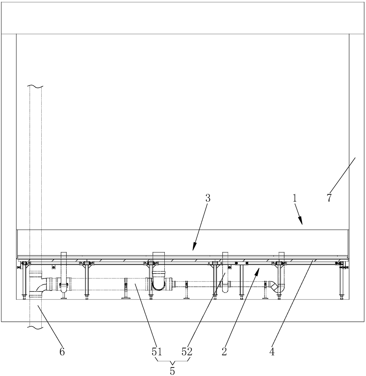
[0053] Such as figure 1 As shown, a prefabricated toilet in this embodiment has a steel frame 2, a flexible waterproof tray 1, a fabricated floor, and a same-layer drain pipe 5. The steel frame 2, flexible waterproof tray 1, a fabricated floor, and the same-layer drain The tubes 5 are all set in the toilet 7.
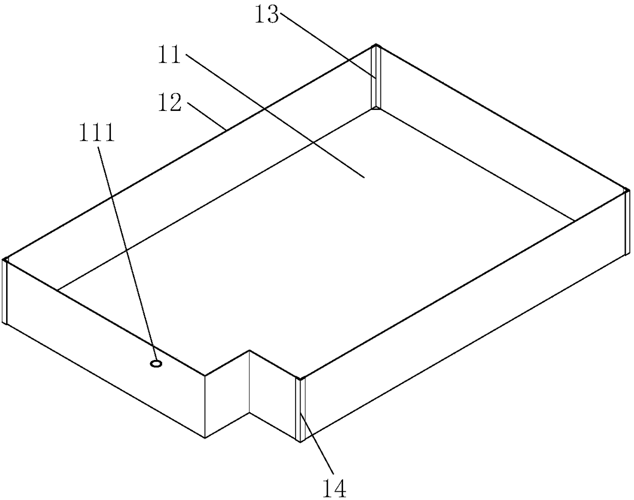
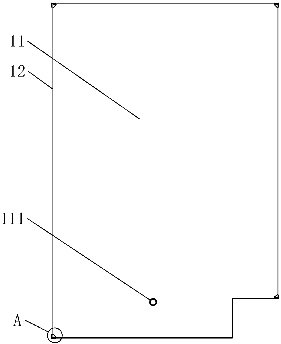
[0054] Such as figure 1 with Figure 13 As shown, in this embodiment, the steel frame 2 is arranged on the upper surface of the toilet 7, and the steel frame 2 has a keel 21, a vertical support frame 22, and a horizontal support frame 23. The keel 21 constitutes a rectangular platform with a gap in one corner and a rectangular platform. The inner keel 21 is in the shape of a grid; the vertical support 22 is used to support the keel 21 and adjust the height of the keel 21, and the horizontal support frame 23 is fixed on the keel 21 on the four sides of the rectangular platform to prevent the keel 21 from moving relative to the wall of the bathroom 7. In this embodiment, the notched corner of the rectangular platform is to avoid pipes or structural columns. In practical applications, the keel 21 in the rectangular platform can also form a network structure of other shapes, such as a diamond or a pattern. The fabricated floor is located on the rectangular platform. Due to the large supporting area of ​​the rectangular platform, the fabricated floor is not easily deformed. Leveling the rectangular platform is equivalent to leveling the fabricated floor. The steel frame 2 is used to level the rectangular platform from the keel 21 The gap is manually leveled, and the leveling difficulty is low. During use, due to the large contact area between the fabricated floor and the keel 21, the fabricated floor is not easy to move horizontally after being stressed, and will not cause water leakage of the drain pipe 5 and shaking of the bathroom floor.
[0055] Such as figure 1 with Figure 13 As shown, in this embodiment, the prefabricated floor includes a first prefabricated floor 4 and a second prefabricated floor 3. The first prefabricated floor 4 is fixed on the upper side of the keel 21; the flexible waterproof tray 1 is set on the first prefabricated floor 4Upper side. In this embodiment, the first assembled floor 4 is used to support the flexible waterproof tray 1 to prevent the flexible waterproof tray 1 from being deformed. In practical applications, the first assembled floor 4 may be a fiber cement board.
[0056] Such as figure 1 with figure 2 As shown, in this embodiment, the flexible waterproof tray 1 includes a waterproof bottom plate 11 and a waterproof vertical plate 12. The waterproof bottom plate 11 is horizontally arranged and has a rectangular shape with a notch in one corner. The waterproof bottom plate 11 is provided with a drain 111 and the waterproof vertical plate 12 Located around the waterproof bottom plate 11, the waterproof bottom plate 11 and the waterproof vertical plate 12 are integrally formed to form an open box shape; the second assembled floor 3 is arranged on the upper side of the waterproof bottom plate 11 of the flexible waterproof tray 1. Specifically, in this embodiment, a corner of the notch of the flexible waterproof tray 1 is to avoid the main drain pipe 6 or the structural column and fit the steel frame 2.
[0057] Such as figure 1 with Figure 13 As shown, in this embodiment, the main drain pipe 51 of the same layer is fixed on the upper surface of the toilet 7 and located below the keel 21, and the drain pipe branch 52 of the same layer passes through the first assembled floor 4, the flexible The waterproof tray 1 and the second assembled floor 3 and the water inlet are located above the second assembled floor 3.
[0058] Such as figure 1 with Figure 13 As shown, in this embodiment, the vertical support frame 22 includes an L-shaped keel support frame 22a, a T-shaped keel support frame 22b, and a cross-shaped keel support frame 22c. The L-shaped keel support frame 22a, the T-shaped keel support frame 22b, and the ten The zigzag keel support frame 22c includes a bending piece, a support column 224 and a height adjustment mechanism 225. The bending piece is fixed on the upper head of the support column 224 and bolted to the keel 21. The height adjustment mechanism 225 is fixed on the lower end of the support column 224. The head is used to adjust the vertical support height of the support column 224 and the bending piece; the transverse support frame 23 is fixed on the keel 21 on the four sides of the rectangular platform. The transverse support frame 23 includes a wall support beam 231 and a wall locking mechanism 232. The upper part of the surface support beam 231 is fixedly connected to the keel 21, and the wall locking mechanism 232 is arranged at the lower part of the wall support beam 231 to prevent the keel 21 from moving relative to the wall. In this embodiment, the steel frame 2 adjusts the height of the keel 21 through the vertical support frame 22. The L-shaped keel support frame 22a is mainly used to support the keel 21 at the corner of the rectangular platform, and the T-shaped keel support frame 22b is mainly used to support the rectangular platform. The keel 21 at the side and the cross-shaped keel support frame 22c are mainly used to support the keel 21 inside the rectangular platform. In this embodiment, two sets of lateral support frames 23 are provided on the keel 21 on the four sides of the steel frame 2 near the wall. The horizontal distance between the keel 21 and the wall is adjusted by the lateral support frame 23 and the movement of the keel 21 is restricted. Therefore, the steel frame structure (Overhead system) The stability is good; specifically, the number and position of the horizontal support frame 23 should be considered according to the shape of the bathroom and the keel 21, as long as the horizontal distance between the keel 21 and the wall can be effectively adjusted and adjusted After finishing, prevent the keel 21 from moving. In this embodiment, the steel frame is sprayed with anti-rust treatment, has a long life span of more than 40 years, and is easy to disassemble.
[0059] Such as Figure 13 to Figure 17 As shown, in this embodiment, the bending piece includes an L-shaped bending piece 221 located on the upper part of the L-shaped keel supporting frame 22a, a T-shaped bending piece 222 located on the upper part of the T-shaped keel supporting frame 22b, and a cross-shaped keel supporting frame. The cross-shaped bending piece 223 at the upper part of 22c. The L-shaped bending piece 221 includes an L-shaped bottom plate 2211 and a vertical plate perpendicular to the L-shaped bottom plate 2211. The L-shaped bottom plate 2211 and the vertical plate together form an L-shaped keel connecting groove with an opening upward. The vertical plates close to the two ends of the L-shaped keel connection groove are provided with keel fixing bolts for connecting the keel; the T-shaped bending piece 222 includes a T-shaped bottom plate 2221 and a vertical plate perpendicular to the T-shaped bottom plate 2221, the T-shaped bottom plate 2221 Together with the vertical plate, a T-shaped keel connection groove with upward openings is formed. The vertical plates near the three ends of the T-shaped keel connection groove are provided with keel fixing bolts for connecting the keel; the cross-shaped bending piece 223 includes a cross-shaped bottom plate 2231 and A vertical plate perpendicular to the cross-shaped bottom plate 2231. The cross-shaped bottom plate 2231 and the vertical plate together form a cross-shaped keel connection groove with an upward opening. The vertical plates near the four ends of the cross-shaped keel connection groove are provided with keel fixings for connecting the keels. bolt. Specifically, in this embodiment, in order to make the bending piece easy to process and have a stable structure, the L-shaped bending piece 221, the T-shaped bending piece 222, and the cross-shaped bending piece 223 are all integrally formed; It is heavy and easy to be stamped and formed. Between the two short vertical plates of the L-shaped bending piece 221, between the T-shaped bending pieces 222 adjacent and perpendicular to each other in the circumferential direction, and the cross-shaped bending piece 223 adjacent to each other in the circumferential direction. There are gaps between the vertical boards. In practical applications, the bending part can also be welded and combined by multiple parts according to actual needs, and the bending part can also adopt other shapes according to actual needs, as long as it does not affect the installation and use.
[0060] Such as Figure 13 to Figure 17 As shown, in this embodiment, the height adjustment mechanism 225 includes a height fixing nut 2251, a height adjustment washer 2252, a height lock nut 2253, and a height adjustment bolt 2254. The height fixing nut 2251 is fixedly connected to the lower end of the support column 224. The adjusting washer 2252 and the height lock nut 2253 are sequentially arranged under the height fixing nut 2251. The height adjustment bolt 2254 includes a head and a threaded part. The threaded part of the height adjusting bolt 2254 passes through the height lock nut 2253 from bottom to top. , Height adjustment washer 2252 and height fixing nut 2251, height lock nut 2253 and height fixing nut 2251 are all matched with the threaded part of height adjustment bolt 2254. Before adjusting the height of the keel 21, first loosen the height lock nut 2253 downwards, and then rotate the height adjustment bolt 2254 to adjust the height of the keel 21. After the height of the keel 21 is adjusted, screw the height lock nut 2253 up.
[0061] Such as Figure 13 with Figure 18 As shown, in this embodiment, the wall locking mechanism 232 includes a wall fixing nut 2321, a wall adjusting washer 2322, a wall locking nut 2323, and a wall leveling bolt 2324. The lower part of the wall support beam 231 is provided with The wall leveling bolt installation hole perpendicular to the wall, the wall fixing nut 2321 is fixed to the wall support beam 231 on the far wall side of the wall leveling bolt installation hole, the wall adjusting washer 2322 and the wall are locked Nuts 2323 are sequentially arranged on the wall side of the wall leveling bolt installation holes; wall leveling bolts 2324 include a head and threaded parts, and the threaded parts of wall leveling bolts 2324 pass through the wall from outside to inside and lock Nut 2323, wall adjusting washer 2322, wall leveling bolt mounting hole and wall fixing nut 2321, wall lock nut 2323 and wall fixing nut 2321 are all compatible with the threaded part of wall leveling bolt 2324 . In this embodiment, the wall leveling bolt 2324 of the wall locking mechanism 232 abuts against the wall of the bathroom 7. Before adjusting the distance between the keel 21 and the wall, first loosen the wall locking nut 2323, and then rotate the wall The leveling bolt 2324 adjusts the distance between the keel 21 and the wall. When the distance between the keel 21 and the wall is adjusted, tighten the wall lock nut 2321 to prevent the keel 21 from moving horizontally.
[0062] Such as Figure 13 to Figure 18 As shown, in this embodiment, both the height adjustment bolt 2254 and the wall leveling bolt 2324 are made of nylon. In order to facilitate the connection of nuts and bolts, the keel 21 and the supporting column 224 are made of rectangular tubes, and the wall supporting beam 231 is made of channel steel. In this embodiment, the height fixing nut 2251 is welded into the square hole at the lower end of the support column 224, and the lower end of the height fixing nut 2251 is flush with the lower end of the support column 224.
[0063] Such as Figure 13 to Figure 18 As shown, in this embodiment, the keel 21 includes a horizontal keel 211 and a longitudinal keel 212, wherein the horizontal keel 211 is arranged in parallel along the length of the rectangular platform, and the longitudinal keel 212 is perpendicular to the horizontal keel 211. In this embodiment, the vertical height of the cross section of the horizontal keel 211 and the vertical keel 212 are the same, and the specifications of the vertical keel 212 and the horizontal keel 211 located at the edge of the grid are the same, and the horizontal keel 211 located in the grid network The cross-sectional width is greater than the cross-sectional width of the transverse keel 211 at the edge of the grid; in order to reduce installation errors, the transverse keel 211 is fixed on all the vertical support frames 22 arranged along the axis of the transverse keel 211, so most of the transverse keel 211 is longer than The length of the longitudinal keel 212 is fixed on two adjacent vertical support frames 22. In this embodiment, in order to increase the support strength of the bending member, in the T-shaped bending member 222, a reinforcing rib plate with a reinforcing structure is provided between the lower side where the T-shaped bottom plate 2221 supports the longitudinal keel 212 and the support column 224; In the cross-shaped bending piece 223, a reinforcing rib plate with a reinforcing structure is provided between the lower side of the cross-shaped bottom plate 2231 supporting the longitudinal keel 212 and the supporting column 224.
[0064] Such as Figure 2 to Figure 10 As shown, in this embodiment, the adjacent waterproof vertical plates 12 of the flexible waterproof tray 1 are connected by hot-melt welding through the female angle electromagnetic connection angle 13 and the male angle electromagnetic connection angle 14, and the female angle electromagnetic connection angle 13 is located adjacent to each other. The inner corner side formed by the two waterproof vertical plates 12, the female corner electromagnetic connection angle 13 is connected to the two adjacent waterproof vertical plates 12 and the upper side of the waterproof bottom plate 11 by heat fusion welding, and the male angle electromagnetic connection angle 14 is located at two adjacent waterproof vertical plates. On the outer corner side formed by the plate 12, the male corner electromagnetic connection corner 14 is thermally welded and connected to the two adjacent waterproof vertical plates 12 and the lower side of the waterproof bottom plate 11. The adjacent waterproof vertical plates 12 of the flexible waterproof tray 1 are connected by hot-melt welding through the female angle electromagnetic connection angle 13 located inside the vertical plate 11 and the male angle electromagnetic connection angle 14 located outside the vertical plate. The operation is simple and the operation is After placing the female angle electromagnetic connecting angle 13 and the male angle electromagnetic connecting angle 14, the electromagnetic welding equipment can be used for electromagnetic induction heating. The installation difficulty is low. The flexible waterproof plate 1 not only has good waterproof performance, but also avoids the thickness variation everywhere. , The overall appearance is beautiful. In practical applications, the internal and external corners can also be bonded to the flexible waterproof disk 1.
[0065] Such as Figure 5 to Figure 10 As shown, in this embodiment, the female corner electromagnetic connecting angle 13 includes a female corner lower connecting plate 131, a female corner upper connecting plate 132, and a female corner electromagnetic mesh surface 133. The female corner lower connecting plate 131 is an isosceles right triangle, and the female corner The upper connecting plate 132 has an L-shaped cross-section, and the lower end is fixedly connected to the two right-angled sides of the female corner lower connecting plate 131, and the female corner electromagnetic mesh surface 133 is arranged on the proximal plate of the female corner lower connecting plate 131 and the female corner upper connecting plate 132 Side; the male angle electromagnetic connection angle 14 includes a male angle lower connecting plate 141, a male angle upper connecting plate 142 and a male angle electromagnetic mesh surface 143, the male angle lower connecting plate 141 is an isosceles right triangle, the male angle upper connecting plate 142 is The L-shaped lower end is fixedly connected to the two right-angle sides of the lower male angle connecting plate 141, and the male angle electromagnetic mesh surface 143 is arranged on the side of the near vertical plate of the male lower connecting plate 141 and the male upper connecting plate 142. In this embodiment, both the internal angle electromagnetic mesh surface 133 and the external angle electromagnetic mesh surface 143 are composed of electrode wires. After electromagnetic induction heating, the electrode wires generate heat to make the internal angle electromagnetic connection angle 13 and the external angle electromagnetic connection angle 14 and the flexible waterproof Disk 1 is connected by hot-melt welding. In order to facilitate installation, the waterproof bottom plate 11, the waterproof vertical plate 12, the female corner lower connecting plate 131, the female corner upper connecting plate 132, the male corner lower connecting plate 141, and the male corner upper connecting plate 142 are all made of HDPE. In order to have a beautiful appearance, the upper ends of the female corner upper connecting plate 132 and the male corner upper connecting plate 142 are flush with the upper end of the waterproof vertical plate 12.
[0066] Such as Picture 11 As shown, in this embodiment, in order to facilitate the connection between the drain outlet 111 of the flexible waterproof tray 1 and the waterproof tray drain pipe 53 and prevent water leakage, the drain outlet 111 is provided with a circular heat sink integrally formed with the waterproof bottom plate 11 and opened downward. Bend.
[0067] Such as Picture 11 As shown, the drainage structure of a flexible waterproof tray of this embodiment has a drain 111, a support pipe 16, an electrode hot-melt elbow 17, and a waterproof tray drain pipe 53, the drain 111 is integrated with the waterproof bottom plate 11 of the flexible waterproof tray 1 The lower part of the support pipe 16 is located in the drain port 111, the lower end of the support pipe 16 is flush with the lower end of the drain port 111 and the upper end exceeds the upper end of the drain port 111, and the upper end of the support pipe 16 is provided with Drainage groove; the inner side of the upper end of the electrode hot melt elbow 17 is provided with an electromagnetic mesh surface, and the lower part of the drain 111 is inserted into the upper end head of the electrode hot melt elbow 17 and then connected with the electrode hot melt elbow 17 by heat welding, and the drainage pipe of the waterproof pan 53 is connected to the lower end of the electrode elbow 17. In the drainage structure of the flexible waterproof tray, the drainage port 111 is integrally formed with the waterproof bottom plate 11 of the flexible waterproof tray 1 and has a downwardly extending annular shape. The electromagnetic mesh surface on the inner side of the upper end of the electrode hot-melt elbow 17 is composed of electrode wires. After the electromagnetic mesh surface is heated by electromagnetic induction, the electrode wire heats up to make the electrode hot-melt elbow 17 and the drainage port 111 hot-melt welding connection, the connection difficulty is low, and the waterproof performance is good; the drainage groove is opened around the upper end of the support pipe to facilitate cleaning And drainage. Specifically, in this embodiment, the drain 111 and the electrode hot-melt elbow 17 are made of HDPE material, and the support pipe 16 and the waterproof tray drain pipe 53 are both PVC pipes; the drain 111 of the flexible waterproof tray 1 passes through the waterproof tray drain pipe 53 Drain the water to the main drain pipe 5 (not shown in the figure) on the same floor.
[0068] Such as Figure 19 As shown, the fabricated floor 3 includes a base plate 31, a positioning net 32, a positioning card, and a tile 33. The positioning net 32 ​​is rectangular and fixed on the upper surface of the base plate 31, and adjacent positioning nets 32 are clamped together; the positioning card includes a A positioning card 34 and a second positioning card 35, the first positioning card 34 is fixed in the middle of the positioning net 32, the second positioning card 35 is fixed at the four corners of the positioning net 32, the tile 33 is composed of adjacent first positioning cards 34 and second positioning cards 34 The positioning card 35 is positioned and adhered to the positioning net 32. In this embodiment, the substrate 31 is a fiber cement board, and the positioning net 32 ​​is made of ABS engineering plastic. In practical applications, the substrate 31 can also be an alloy plate.
[0069] Such as figure 1 with Figure 19 As shown, the fabricated floor 3 first fixes the base plate 31 on the steel frame 32, and then clamps and fixes the positioning nets 32 on the base plate 31. After applying tile glue on the positioning nets 32, the first positioning card 34 The second positioning card 35 is connected to the positioning net 32. At this time, the tile 33 can be easily installed by positioning the adjacent first positioning card 34 and the second positioning card 35, which reduces the difficulty of installing the tile 33 and improves the quality of the tile 33. Installation efficiency, the tile 33 can be installed evenly without the need for professional personnel. Specifically, the gaps between adjacent tiles 33 are filled with a caulking agent; in this embodiment, the positioning net 32 ​​and the base plate 31 are fixedly connected by gun nails. In practical applications, ordinary nails can also be used for connection, as long as it does not affect the installation And use it.
[0070] Such as Figure 19 to Figure 21 As shown, in this embodiment, the middle of the positioning net 32 ​​is provided with a first card hole 321, the lower part of the first positioning card 34 is clamped in the first card hole 321 and the upper part exceeds the upper surface of the positioning net 32, and the lower part of the first positioning card 34 Fits with the first card hole 321. The second positioning card 35 includes a supporting part 351 and a limiting part 352. The four corners of the positioning net 32 ​​are provided with bayonet openings. The supporting parts 351 are adapted to the bayonet and clamped at the four corners of the positioning net 32. The supporting parts 351 The thickness is the same as the thickness of the positioning net 32. Specifically, in this embodiment, the first positioning card 34, the first card hole 321, and the limiting portion 352 are all cross-shaped; the bayonet and the supporting portion 352 are all rectangular. In actual applications, the first positioning card 34, the first card hole 321, and the limiting portion 352 may also adopt other shapes, as long as it does not affect the installation and use.
[0071] Such as Figure 1 to Figure 21 As shown, a prefabricated toilet installation method includes the following steps:
[0072] Step S1, measure the size of the bathroom, and prefabricate the steel frame 2 according to the size of the bathroom;
[0073] Step S2, laying the same-layer drainage pipe 5;
[0074] Step S3, install the steel frame 2. Step S5 includes the following steps: Step S3.1, adjust the vertical support frame 22 to a uniform height; Step S3.2, connect the keel 21 to the vertical support frame 22 ( The horizontal keel 211 can be connected first, and after all the horizontal keels 211 are connected to the corresponding vertical support frame 22, the longitudinal keel 212 can be connected); step S3.3, adjust the distance between the keel 21 on the four sides of the rectangular platform and the wall ( Prevent the four sides of the rectangular platform from being too close or too far away from the wall); Step S3.4, fine-tune the height of the vertical support frame 22 so that the upper side of the keel 21 is on the same horizontal plane (measure the level of the keel 21 by the horizontal ruler while adjusting the existing Deviation of the height of the vertical support frame 22); step S3.5, lock the distance between the keel 21 on the four sides of the rectangular platform and the wall through the lateral support frame 23;
[0075] Step S4, install the first assembled floor 4;
[0076] Step S5, install the flexible waterproof tray 1, wherein step S5 includes the following steps: Step S5.1, cut the flexible coiled material according to the size of the bathroom and form the original shape of the flexible waterproof tray 1, the original shape of the flexible waterproof tray ( Picture 12 ) Is composed of an integrally formed waterproof bottom plate 11 and a waterproof vertical plate 12. The shape of the waterproof bottom plate 11 is the same as the plan shape of the toilet, and the waterproof vertical plate 12 is located around the waterproof bottom plate 11; step S5.2, the waterproof vertical plate 12 is bent along the heat The line 15 is bent to make the waterproof vertical board 12 and the waterproof bottom plate 11 form a box shape with an upper opening; step S5.3, place a male electromagnetic connection angle 14 on the outer corner formed by the two adjacent waterproof vertical boards 12 that need to be connected , Place the female corner electromagnetic connecting corner 13 on the inner corner formed by the two adjacent waterproof vertical plates 12 that need to be connected; step S5.4, use a clamp to electromagnetically connect the female corner 13, and the two adjacent waterproof vertical plates that need to be connected Clamp 12 and the male angle electromagnetic connection angle 14 at the same time to maintain a continuous clamping force between the female angle electromagnetic connection angle 13 and the male angle electromagnetic connection angle 14; step S5.5, give the female angle electromagnetic connection angle 13 and the male angle The electromagnetic connection angle 14 is heated by electromagnetic induction at the same time, and the electromagnetic connection angle 14 of the male angle is between the electromagnetic mesh surface 133 side of the internal angle electromagnetic connection angle 13 and the two adjacent waterproof vertical plates 12 and the upper side of the waterproof bottom plate 11 The electromagnetic induction heating is stopped after the electromagnetic induction heating is stopped after the welding connection between the side of the electromagnetic mesh surface 143 and the two adjacent waterproof vertical plates 12 and the lower side of the waterproof bottom plate 11; step S5.6, processing the drain port 111, so that the drain port 111 is formed with The waterproof bottom plate 11 is integrally formed with a circular ring with the opening downward; step S5.7, connect the drain 111 with the main drain pipe 6; step S5.8, put the flexible waterproof plate 1 on the leveling cushion 4;
[0077] Step S6, install the fabricated floor 3, where step S6 includes the following steps: step S6.1, install the base plate 31; step S6.2, install the positioning net 32, fix the positioning net 32 ​​to the upper surface of the base plate 31, and position adjacent ones The nets 32 are clamped; step S6.3, pour the tile glue into the positioning net 32, and scrape it flat; step S6.4, clamp the first positioning card 34 in the middle of the positioning net 32, and attach the second positioning card 35 It is clamped at the four corners of the positioning net 32; step S6.5, positioning the paving tiles 33 according to the first positioning card 34 and the second positioning card 35;
[0078] Step S7, security check.
[0079] In step S6, the shape of the base plate 31 and the tile 33 where the drain pipe 5 of the same layer passes through is adapted to the shape of the drain pipe 5 of the same layer, and the positioning net 32 ​​here must be manually cut when installing.
[0080] The preferred embodiments of the present invention are described in detail above. It should be understood that those of ordinary skill in the art can make many modifications and changes according to the concept of the present invention without creative work. Therefore, all technical solutions that can be obtained by those skilled in the art through logical analysis, reasoning or limited experiments based on the concept of the present invention on the basis of the prior art should fall within the protection scope determined by the claims.

PUM

no PUM

Description & Claims & Application Information

We can also present the details of the Description, Claims and Application information to help users get a comprehensive understanding of the technical details of the patent, such as background art, summary of invention, brief description of drawings, description of embodiments, and other original content. On the other hand, users can also determine the specific scope of protection of the technology through the list of claims; as well as understand the changes in the life cycle of the technology with the presentation of the patent timeline. Login to view more.

Similar technology patents

Method for improving shale gas well recovery ratio on basis of air knocking

InactiveCN102828735AThe equipment process is simpleEasy construction
Owner:CHINA UNIV OF PETROLEUM (EAST CHINA)

Method for constructing wet-operation details of completely-decorated housings

InactiveCN102758504AEasy constructionGood construction effect
Owner:ZHENHUA GROUP KUSN CONSTR ENG

Classification and recommendation of technical efficacy words

  • Less disturbance upstairs and downstairs
  • Easy construction

Fabricated toilet and installation method thereof

PendingCN108442738AEasy constructionLess disturbance upstairs and downstairs
Owner:重庆互邦莱装配式建筑工程有限公司

Steel-encased concrete composite beam-steel pipe column connection joint

InactiveCN105569191AReduce welding workloadEasy construction
Owner:ANHUI HONGLU STEEL CONSTR (GROUP) CO LTD +1

High abrasion-proof PU printing ink for silicon rubber surface

InactiveCN101153139AEasy constructiongood adhesion
Owner:东莞市贝特利新材料有限公司

Air foam slug flow driving process for oil recovery of oil field

InactiveCN102061906ASimplify construction stepsEasy construction
Owner:YANCHANG OIL FIELD
Why Eureka
Try Eureka