Semi-persistent scheduling method, network equipment and terminal equipment

A semi-static scheduling and network equipment technology, applied in the field of communication, can solve problems such as low resource utilization and prolonged SPS data transmission

Active Publication Date: 2018-08-14
HUAWEI TECH CO LTD
View PDF4 Cites 19 Cited by
  • Summary
  • Abstract
  • Description
  • Claims
  • Application Information

AI Technical Summary

Problems solved by technology

However, in practical applications, when SPS data is transmitted in units of subframes, there are often unused resources in subframes, which leads to low resource utilization when SPS is used in related technologies
In addition, since SPS data is transmitted in units of subframes in the related art, the transmission delay of SPS data is fixed at 1 ms, which results in a longer transmission delay of SPS data

Method used


Image

  • Semi-persistent scheduling method, network equipment and terminal equipment
  • Semi-persistent scheduling method, network equipment and terminal equipment
  • Semi-persistent scheduling method, network equipment and terminal equipment

Examples


specific Embodiment 1

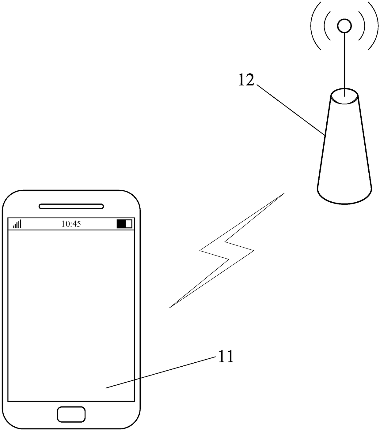
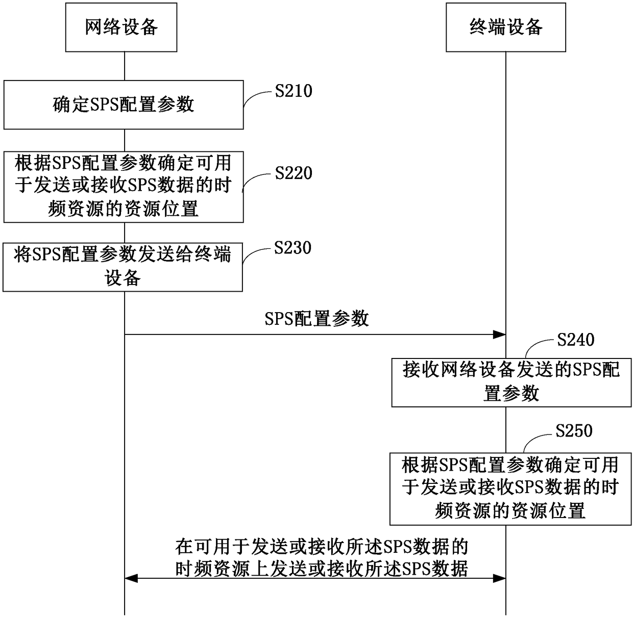
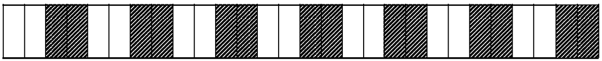
[0130] When the network device 12 sends SPS data to the terminal device 11, that is, when downlink SPS data is transmitted between the network device 12 and the terminal device 11, the network device 12 uses formula (1) to calculate the time-frequency resources that can be used to send SPS data. position, the terminal device 11 uses formula (1) to calculate the resource position of the time-frequency resource that can be used to receive SPS data. Among them, the formula (1) is as follows:

[0131] (10*SFN*slot_number+subframe*slot_number+slot_id)=[(10*slot_number*SFNstart time+slot_number*subframestart time+slot_idstart time)+N*semiPersistSchedIntervalDL] modulo 10240*slot_number (1)

[0132] In formula (1), the full English name of SFN is system frame number, which is used to represent the system frame number (that is, the number of wireless frames), subframe is used to represent the subframe number, and slot_id is used to represent the short subframe number in the subframe ...

specific Embodiment 2

[0138] When the terminal device 11 sends SPS data to the network device 12, that is, when the network device 12 and the terminal device 11 perform uplink SPS data transmission, the network device 12 uses formula (2) to calculate the resources of time-frequency resources that can be used to receive SPS data location, the terminal device 11 uses formula (2) to calculate the resource location of the time-frequency resource that can be used to send SPS data. Among them, formula (2) is as follows:

[0139] (10*SFN*slot_number+subframe*slot_number+slot_id)=[(10*slot_number*SFNstart time+slot_number*subframestart time+slot_idstart time)+N*semiPersistSchedIntervalUL+Subframe_Offset*(Nmodulo 2)]modulo 10240*slot_number (2)

[0140]In formula (2), the full English name of SFN is system frame number, which is used to represent the system frame number (that is, the number of wireless frames), subframe is used to represent the subframe number, and slot_id is used to represent the short sub...


PUM


Abstract

The embodiments of the invention disclose a semi-persistent scheduling method, network equipment and terminal equipment, wherein the method comprises the following steps: the network equipment determines a semi-persistent scheduling SPS configuration parameter, wherein the SPS configuration parameter comprises SPS period length, symbol information and an SPS activation command; the SPS activationcommand is used for indicating a system frame number and a subframe number where a first time-frequency resource, which can be used for sending or receiving SPS data, is located; the symbol information is used for indicating the position of the symbol occupied by the time-frequency resource for sending or receiving the SPS data in the subframe; the network equipment determines the resource position of the time-frequency resource which can be used for sending or receiving the SPS data according to the SPS period length, the symbol information and the SPS activation command; and the network equipment sends the SPS configuration parameter to the terminal equipment. According to the technical scheme of the embodiments in the invention, the resource utilization rate of the semi-persistent scheduling can be improved, and the transmission delay of the SPS data can be reduced.

Description

technical field [0001] The present invention relates to the field of communication technology, in particular to a semi-static scheduling method, network equipment and terminal equipment. Background technique [0002] In the Long Term Evolution (LTE) system, due to the high flexibility of dynamic scheduling, it can improve the utilization rate of wireless frequency bands, guarantee the quality of service (Quality of Service, QOS) of users, and improve the system capacity, so dynamic scheduling is an LTE system. The most basic scheduling method in . In dynamic scheduling, resource allocation adopts an on-demand allocation method, and each scheduling requires the interaction of scheduling signaling. For services with inconspicuous burst characteristics and high real-time performance, network equipment is required to schedule terminal equipment at each transmission time interval (Transmission Time Interval, TTI), and the scheduling information is transmitted on the Physical Dow...

Claims


Application Information

Patent Timeline
Patent Type & Authority Applications(China)
IPC IPC(8): H04W72/12
CPCH04W72/12H04W72/0446H04W72/0453H04L5/0044H04L5/0092H04W72/23H04W72/04
Inventor 苗金华权威许斌柴丽张戬
Owner HUAWEI TECH CO LTD
Why Eureka
Try Eureka