Textile slurry mixing device on basis of gear and rack lifting

A technology of rack and pinion and textile pulp, which is applied to mixers with rotating stirring devices, mixers, shaking/oscillating/vibrating mixers, etc., which can solve labor-intensive, time-consuming, labor-intensive, applicability and practical limitations and other problems, to achieve the effect of increasing the mixing effect, improving the mixing effect, and changing the disturbance range

Inactive Publication Date: 2018-08-17
绍兴柯桥双典纺织有限公司
View PDF0 Cites 3 Cited by
  • Summary
  • Abstract
  • Description
  • Claims
  • Application Information

AI Technical Summary

Problems solved by technology

In the production process of textile size, it is generally necessary to mix the textile size with the color paste, and its mixing uniformity is directly related to the quality of the textile size. In the prior art, the mixing of the textile size and the color paste is largely manual stirring, and its It is artificial use of sticks for stirring. Although it can complete the mixing of textile pulp and color paste, it is time-consuming and labor-intensive, labor-intensive, and it is not easy to stir evenly, which will affect the quality, applicability and quality of textile pulp to a certain extent. Practicality is somewhat limited

Method used


Image

  • Textile slurry mixing device on basis of gear and rack lifting
  • Textile slurry mixing device on basis of gear and rack lifting
  • Textile slurry mixing device on basis of gear and rack lifting

Examples


Embodiment Construction

[0018] The following will clearly and completely describe the technical solutions in the embodiments of the present invention with reference to the accompanying drawings in the embodiments of the present invention. Obviously, the described embodiments are only some, not all, embodiments of the present invention. Based on the embodiments of the present invention, all other embodiments obtained by persons of ordinary skill in the art without making creative efforts belong to the protection scope of the present invention.

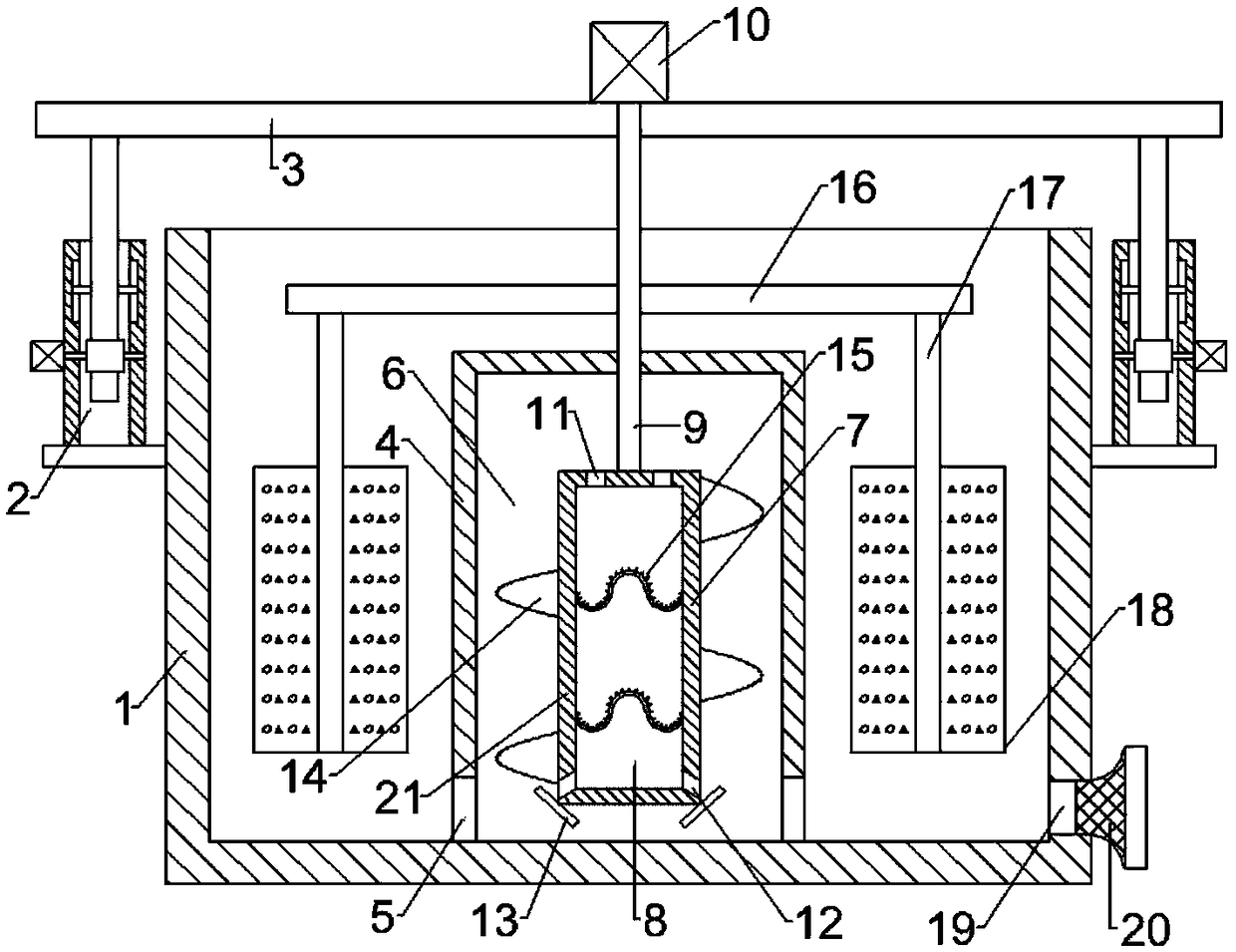
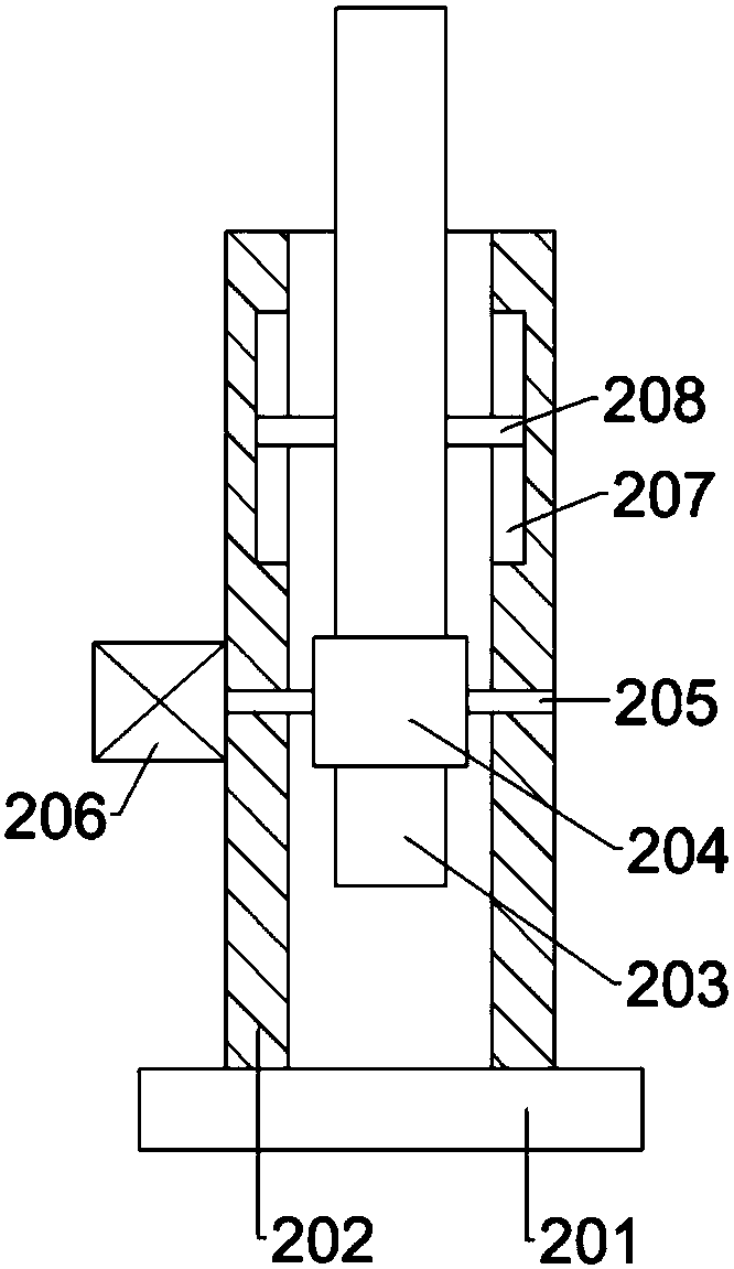
[0019] see Figure 1-Figure 4 , in an embodiment of the present invention, a textile slurry mixing device based on rack and pinion lifting, including a housing 1, and a rack and pinion lifting device 2 is arranged on the outer wall of the housing 1, and the rack and pinion lifting device 2 The device 2 includes a mounting base 201, a sleeve 202 is fixedly connected to the mounting base 201, a rack 203 is arranged inside the sleeve 202, a gear 204 is engaged on...


PUM


Abstract

The invention discloses a textile slurry mixing device on the basis of gear and rack lifting. The textile slurry mixing device comprises a shell. Gear and rack lifting devices are arranged on the outer side wall of the shell and comprise mounting seats, sleeves are fixedly connected onto the mounting seats, racks are arranged in the sleeves, gears mesh with the front sides of the racks, first rotary shafts are fixedly connected onto the gears and are erected on the sleeves, and the outer ends of the first rotary shafts are fixedly connected with output shafts of first motors; a first cylinderis fixedly connected to the middle of the inner bottom of the shell, and a first cavity is arranged inside the first cylinder. The textile slurry mixing device has the advantages that the gears can bedriven by the first motors to rotate, the racks which mesh with the gears can upwardly move, and accordingly a support plate can rise; elevated materials can be fed into a second cavity via feed through holes, then can be ejected from discharge through holes and can be collided with barriers in ejection procedures, and accordingly materials can be uniformly and effectively mixed and treated by the aid of the textile slurry mixing device.

Description

technical field [0001] The invention relates to the technical field of textile machinery, in particular to a textile slurry mixing device based on a rack and pinion lift. Background technique [0002] The original meaning of textile is taken from the general term of spinning and weaving, but with the continuous development and improvement of the textile knowledge system and subject system, especially after the emergence of non-woven textile materials and three-dimensional composite weaving technologies, the current textile is not only a traditional Hand spinning and weaving also include garment, industrial and decorative textiles produced by non-woven technology, modern three-dimensional weaving technology, and modern electrostatic nano-netting technology. Therefore, modern textile refers to a multi-scale structure processing technology of fibers or fiber aggregates. Ancient Chinese textile and printing and dyeing technology has a very long history. As early as the primitiv...

Claims


Application Information

Patent Timeline
Patent Type & Authority Applications(China)
IPC IPC(8): B01F7/16B01F11/00
CPCB01F27/192B01F27/2322B01F27/851B01F27/806B01F31/443B01F31/449B01F31/441
Inventor 何艺斓
Owner 绍兴柯桥双典纺织有限公司
Why Eureka
Try Eureka