Drilling processing and fixing device and method for brake drum

A technology of a fixing device and a fixing method, which is applied in the field of brake drum drilling and fixing devices, and can solve problems such as difficulty in guaranteeing machining accuracy of a cylindrical drum body, inaccurate positioning of brake drum drilling, and easy jumping of brake drums, etc. Problems, to achieve dimensional accuracy, easy to control, prevent jumping, and withstand firm effects

Inactive Publication Date: 2018-08-17
JIANGXI JIUWANG AUTO PARTS MFG CO LTD
View PDF8 Cites 9 Cited by
  • Summary
  • Abstract
  • Description
  • Claims
  • Application Information

AI Technical Summary

Problems solved by technology

The processing accuracy of the cylindrical drum body of the brake drum is difficult to guarantee. Positioning and drilling according to the drum body will cause the accumulation of errors and affect the processing accuracy; during the drilling process, the brake drum is not fixed firmly, which affects the dimensional accuracy of the hole ;When the drilling bit and the brake drum are just in contact, the brake drum is prone to beating, which affects the processing accuracy
[0004] The Chinese patent with the patent application number "201010280668.8" discloses a "brake drum processing tooling", which has the beneficial effect of improving the braking surface of the car, but this technology still has the problem of inaccurate positioning of the brake drum drilling and processing. Defects that are not firmly fixed

Method used


Image

  • Drilling processing and fixing device and method for brake drum
  • Drilling processing and fixing device and method for brake drum
  • Drilling processing and fixing device and method for brake drum

Examples


Embodiment 1

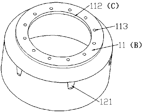
[0069] Such as image 3 , Figure 4 As shown, the brake drum is a drum-shaped structure, hollow, including the flange, that is, the drilling plane 11 (B), the braking surface circumference of the brake drum 12 (H), the bottom end surface of the braking surface circumference of the brake drum 13 (D); the flange process requires a flat surface structure, including the lower end surface 111 (E) of the flange, the upper end surface and the flange seam 112 (C) are all required to be a flat surface structure; the braking surface of the brake drum There is a groove 121 on the circumference 12 (H); a hole needs to be drilled on the drilling plane (B), which is the hole 113; the flange seam (C) is also required to be a perfect circular structure, and the peripheral surface is flat.

[0070] The brake drum application process has high requirements on the shape and dimensional accuracy of the flange seam (C), as well as the position and dimensional accuracy of the hole 113, and, for the...

Embodiment 2

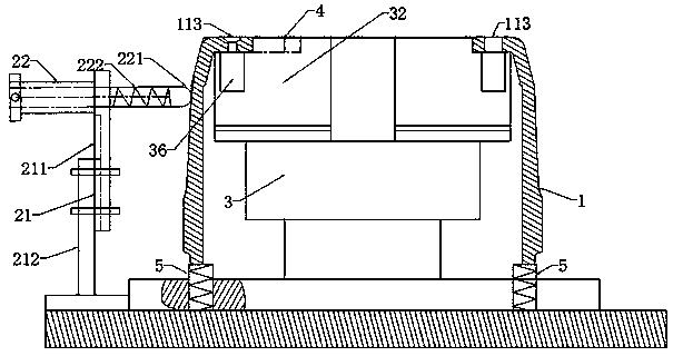
[0081] Such as figure 1 As shown, a brake drum drilling and fixing device includes an internal positioning device and an external positioning device; the internal positioning device includes a chuck 3 and a tooling 4, the chuck 3 is fixed on the table, and the chuck 3 is provided with claws 32 , the claw 32 is connected to the chuck 3 and supported by the chuck 3, the claw 32 is driven by the driving mechanism to extend outward, the claw 32 supports the brake drum flange (drilling plane) 11 (B) upward, and the tooling 4 is fixed and installed On the claw 32, the outside of the tooling 4 is a circular arc surface structure, and it withstands the stop of the brake drum flange (inner peripheral surface of the drilling plane) 112 (C); the external positioning device includes a column 21 and a push rod 22. The column 21 is vertically fixed on the table, the top of the column 21 is connected to the ejector rod 22, and the head 221 of the front end of the ejector rod is an arc-shaped...

Embodiment 3

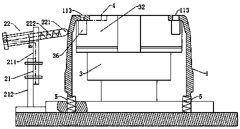
[0087] Such as figure 2 As shown, a brake drum drilling and fixing device includes an internal positioning device and an external positioning device; the internal positioning device includes a chuck 3 and a tooling 4, the chuck 3 is fixed on the table, and the chuck 3 is provided with claws 32 , the claw 32 is connected to the chuck 3 and supported by the chuck 3, the claw 32 is driven by the driving mechanism to extend outward, the claw 32 supports the brake drum flange (drilling plane) 11 (B) upward, and the tooling 4 is fixed and installed On the claw 32, the outside of the tooling 4 is a circular arc surface structure, and it withstands the stop of the brake drum flange (inner peripheral surface of the drilling plane) 112 (C); the external positioning device includes a column 21 and a push rod 22. The column 21 is vertically fixed on the table, the top of the column 21 is connected to the ejector rod 22, and the head 221 of the front end of the ejector rod is an arc-shape...


PUM


Abstract

The invention belongs to the field of automobile part processing and discloses a drilling processing and fixing device and method for a brake drum. The device comprises a chuck and a tool of an internal positioning device and comprises an upright post and an ejector rod of an external positioning device. The drilling processing and fixing device and method are accurate in positioning and drillingposition, high in dimensional accuracy, firm in fixing effect and wide in applicability.

Description

technical field [0001] The invention belongs to the field of auto parts processing, and in particular relates to a brake drum drilling and fixing device and method. Background technique [0002] In the process of brake drum processing of auto parts, the processing of the braking surface is very critical, including the drilling of the braking surface, the positioning and size of the hole, which directly affects the processing quality of the product. [0003] In the traditional brake drum processing process, the cylindrical brake drum body of the brake drum is usually clamped by a chuck, and then the brake drum is drilled from the upper part. The processing accuracy of the cylindrical drum body of the brake drum is difficult to guarantee. Positioning and drilling according to the drum body will cause the accumulation of errors and affect the processing accuracy; during the drilling process, the brake drum is not fixed firmly, which affects the dimensional accuracy of the hole ...

Claims


Application Information

Patent Timeline
Patent Type & Authority Applications(China)
IPC IPC(8): B23Q3/06B23Q3/08B23B31/16
Inventor 谢小忠李忠文卢培贵
Owner JIANGXI JIUWANG AUTO PARTS MFG CO LTD
Why Eureka
Try Eureka