
Improved vehicle-mounted electronic device

An improved technology for on-board electronics, applied in vehicle components, transportation and packaging, etc., can solve problems such as poor power supply security, threats to the safety of people on board, and flying off of on-board electronic equipment, and achieve the effect of convenient operation and simple structure

Inactive Publication Date: 2018-08-17
广州正顺机械技术开发有限公司
View PDF3 Cites 0 Cited by
  • Summary
  • Abstract
  • Description
  • Claims
  • Application Information

AI Technical Summary

Problems solved by technology

[0002] Due to its convenience, improved on-board electronic devices are widely used, including on-board mobile phone holders, on-board computers, on-board USB charging treasures, on-board audio, on-board TVs, etc.; car users can use portable improved on-board electronic devices through simple brackets or brackets. For fixing, its structural design is usually to use hooks and buckles to fix various improved on-board electronic equipment, so that various improved on-board electronic equipment with different models and sizes can be used. However, once the car encounters an emergency, such as braking , acceleration, and collision, the brackets or brackets used to fix the improved on-board electronic equipment are easily damaged, so that the improved on-board electronic equipment will fly off the brackets or brackets, directly threatening the safety of people on board, and the safety of power supply Therefore, there is an urgent need for an improved vehicle-mounted electronic device that is convenient for quick disassembly and safe power supply

Method used


Image

  • Improved vehicle-mounted electronic device
  • Improved vehicle-mounted electronic device
  • Improved vehicle-mounted electronic device

Examples


Embodiment Construction

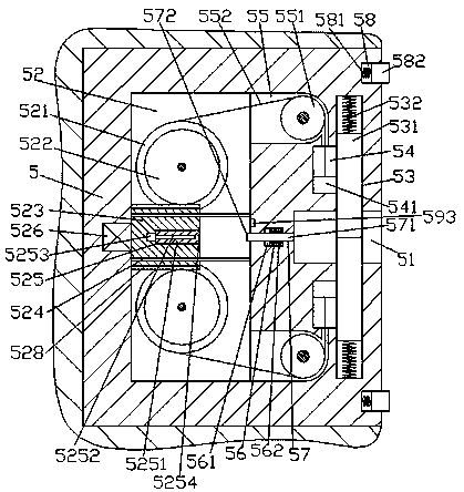
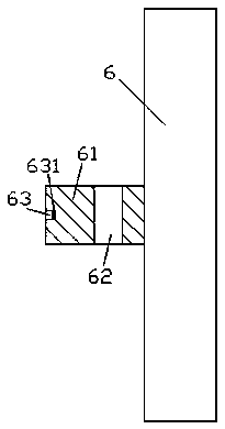
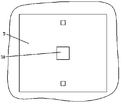
[0013] Combine below Figure 1-Figure 3 The present invention will be described in detail.

[0014] refer to Figure 1-Figure 3 , an improved vehicle-mounted electronic device according to an embodiment of the present invention, including a fixed seat body 5 fixedly installed in the vehicle body and an electronic device main body 6 for mating connection with the fixed seat body 5, the fixed seat body 5. An installation groove 51 is provided in the end surface on the right side, and a drive cavity 52 is provided in the inner wall of the fixed seat body 5 on the left side of the installation groove 51. The upper and lower inner walls of the installation groove 51 Symmetry is provided with countersunk chute 53, and the inside of described countersunk chute 53 is slidably connected with stopper 531, and the side of described countersunk chute 53 is far away from described installation groove 51 and is provided with described stopper 531 pushes against the first spring 532 that i...


PUM


Abstract

The invention provides an improved vehicle-mounted electronic device which comprises a fixed seat body fixedly installed in a vehicle body and an electronic device body used for being connected with the fixed seat body in a matched mode. An installation connection groove is formed in the end face on the right side of the fixed seat body. A drive cavity is formed in the position, on the left side of the installation connection groove, in the inner wall body of the fixed seat body. Countersunk sliding grooves are symmetrically formed in the inner walls on the upper side and the lower side of theinstallation connection groove. A sliding stop board is connected to the inside of each countersunk sliding groove in a sliding fit mode. A first spring used for being connected with the corresponding sliding stop board in an ejection sliding fit mode is arranged on the side, away from the installation connection groove, of each countersunk sliding groove. Sliding guide grooves are formed in theinner walls on the left sides of the countersunk sliding grooves. Sliding guide blocks connected with the sliding stop boards in a stationary fit mode are connected to the inner portions of the sliding guide grooves in a sliding fit mode. Movable cavities extending to the right side are symmetrically formed in the inner walls on the right sides of the upper side and the lower side of the drive cavity. The sides, away from the drive cavity, of the movable cavities communicate with the sliding guide grooves.

Description

technical field [0001] The invention relates to the technical field of vehicle equipment, in particular to an improved vehicle electronic equipment. Background technique [0002] Due to its convenience, improved on-board electronic devices are widely used, including on-board mobile phone holders, on-board computers, on-board USB charging treasures, on-board audio, on-board TVs, etc.; car users can use portable improved on-board electronic devices through simple brackets or brackets. For fixing, its structural design is usually to fix various improved on-board electronic devices by means of hooks and buckles, so that various improved on-board electronic devices with different models and sizes can be used. However, once the car encounters an emergency, such as braking , acceleration, and collision, the brackets or brackets used to fix the improved on-board electronic equipment are easily damaged, so that the improved on-board electronic equipment will fly off the bracket or br...

Claims


Application Information

Patent Timeline
Patent Type & Authority Applications(China)
IPC IPC(8): B60R11/02
CPCB60R11/02B60R2011/0075
Inventor 邹承针詹胜超
Owner 广州正顺机械技术开发有限公司
Learn More