Oil extraction auxiliary conveying equipment

A technology of oil extraction and transportation equipment, which is applied in the direction of extraction fluid, earthwork drilling, measurement, etc., and can solve problems such as pipeline blockage, easy cleaning that cannot be cleaned in time, and reduced oil extraction efficiency

Active Publication Date: 2018-08-17
山东金博石油装备有限公司
View PDF7 Cites 16 Cited by
  • Summary
  • Abstract
  • Description
  • Claims
  • Application Information

AI Technical Summary

Problems solved by technology

[0004] Aiming at the deficiencies in the prior art, the purpose of the present invention is to provide an auxiliary conveying equipment for oil exploitation to solve the problem that when the prior art is used, ...

Method used


Image

  • Oil extraction auxiliary conveying equipment
  • Oil extraction auxiliary conveying equipment
  • Oil extraction auxiliary conveying equipment

Examples


Embodiment Construction

[0023] In order to make the technical means, creative features, goals and effects achieved by the present invention easy to understand, the present invention will be further described below in conjunction with specific embodiments.

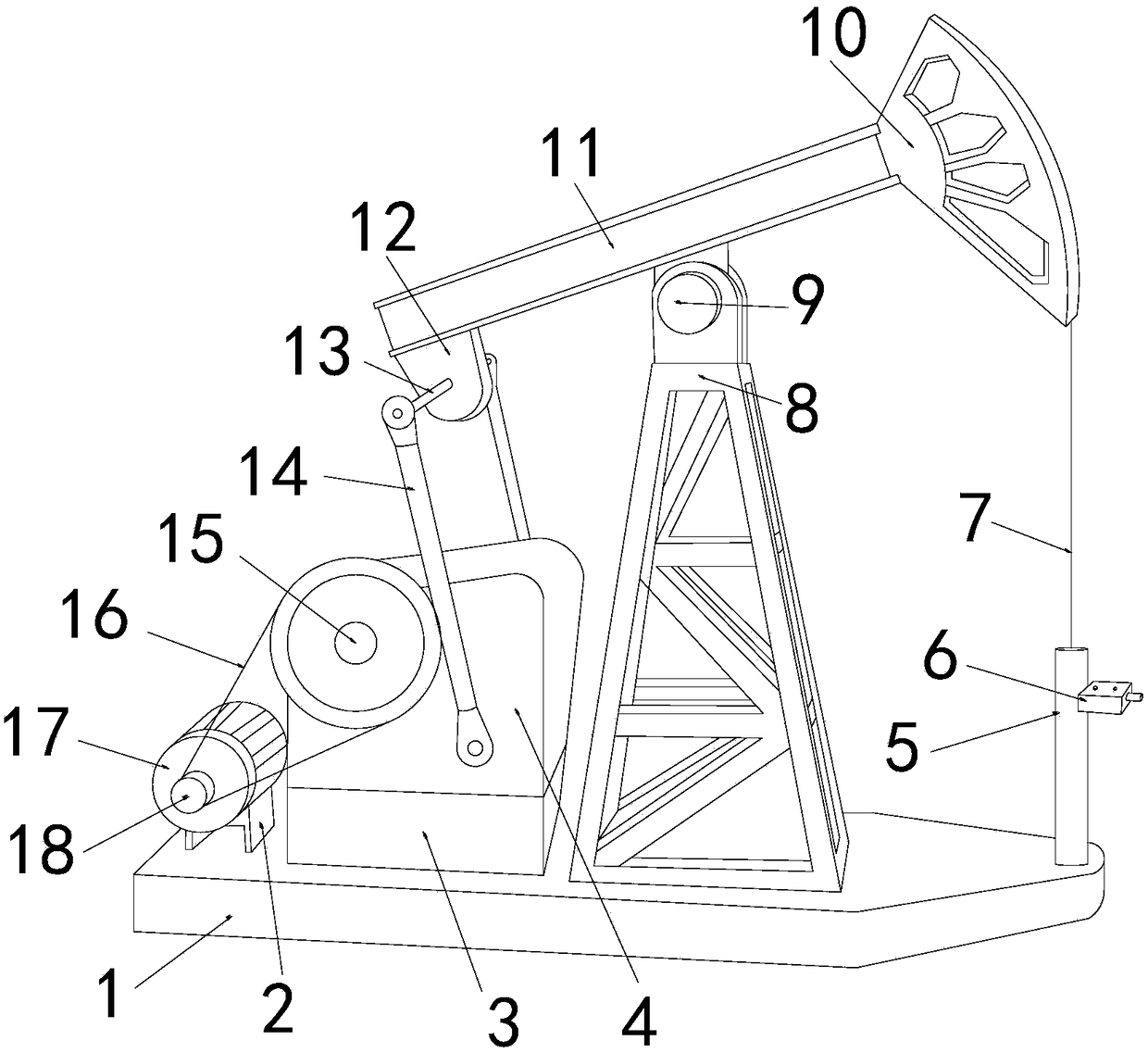
[0024] see Figure 1-Figure 6, the present invention provides a technical solution for auxiliary transportation equipment for oil exploitation: its structure includes a base 1, a base 2, a base 3, a reduction box 4, an oil pipe 5, a detector 6, a stay rope 7, a bracket 8, central axis 9, donkey head 10, beam 11, tail shaft 12, connecting rod 13, support rod 14, No. 1 transmission wheel 15, No. 1 transmission belt 16, motor 17, No. 2 transmission wheel 18, the No. 1 The base 2 is located at the left end of the top surface of the base 1, and is welded with the top surface of the base 1. The top surface is provided with a motor 17, which is an integrated structure with the bottom surface of the motor 17. One end of the motor 17 is provided with a No....


PUM


Abstract

The invention discloses oil extraction auxiliary conveying equipment. The oil extraction auxiliary conveying equipment structurally comprises a bottom seat, a first base, a second base, a speed reducer, an oil pipe, a detector, a first pull rope, a bracket, a middle shaft, a horsehead, a walking beam, a tail shaft, a connecting rod, a supporting rod, a first transmission wheel, a first transmission belt, a motor and a second transmission wheel. The first base is arranged at the left end of the top surface of the bottom seat. The first base and the top surface of the bottom seat are welded. Thetop surface of the first base is provided with the motor, and the top surface of the first base and the bottom surface of the motor are of an integrated structure. One end of the motor is provided with the second transmission wheel, and one end of the motor and one end of the second transmission wheel are of an integrated structure. The second base is arranged at the right end of the first base.The bottom surface of the second base and the top surface of the bottom seat are welded. The bracket is arranged at the right end of the second base. The bottom surface of the bracket and the top surface of the bottom seat are welded. According to the oil extraction auxiliary conveying equipment, through mutual combining of the parts, by additionally arranging mechanisms such as a third pull ropeand a second spring, waste can be automatically discharged and alarming can be automatically conducted when the equipment detects the waste, so that the service life of the equipment is prolonged, andmeanwhile, the oil extraction efficiency is improved.

Description

technical field [0001] The invention is an auxiliary conveying device for petroleum exploitation, which belongs to the field of petroleum exploitation. Background technique [0002] Oil extraction refers to the act of digging and extracting oil in places where oil is stored. In the process of oil extraction, oil and gas flow from the reservoir to the bottom of the well, and then rise from the bottom of the well to the wellhead. [0003] The prior art discloses that the application number is: 201720611873.5, and the present invention discloses an auxiliary transportation equipment for oil exploitation, which includes a device body, a heating chamber is provided at the top of the device body, an oil inlet is provided at the top of the heating chamber, and one end of the heating chamber There is an oil outlet, the middle of the oil outlet is provided with a valve, the inner wall of the heating chamber is provided with a temperature sensor, one side of the heating chamber is pr...

Claims


Application Information

Patent Timeline
IPC IPC(8): E21B43/12E21B43/34E21B47/00
CPCE21B43/121E21B43/34E21B47/00
Inventor 连雪琼
Owner 山东金博石油装备有限公司
Why Eureka
Try Eureka