Connecting structure of electromagnetic valve and water in-out pipeline

A connection structure and water inlet pipe technology, which is applied to the valve shell structure, valve details, multi-way valve, etc., can solve the problems of easy installation and reverse installation, high requirements for the installation environment, and large volume.

Pending Publication Date: 2018-08-17
ZHEJIANG DAWEI ELECTRONICS
View PDF9 Cites 0 Cited by
  • Summary
  • Abstract
  • Description
  • Claims
  • Application Information

AI Technical Summary

Problems solved by technology

In the prior art solenoid valve, the water inlet pipe and the water outlet pipe generally extend toward the opposite direction or the same side on both sides of the valve body. The water pipes are ...

Method used


Image

  • Connecting structure of electromagnetic valve and water in-out pipeline
  • Connecting structure of electromagnetic valve and water in-out pipeline
  • Connecting structure of electromagnetic valve and water in-out pipeline

Examples


Embodiment Construction

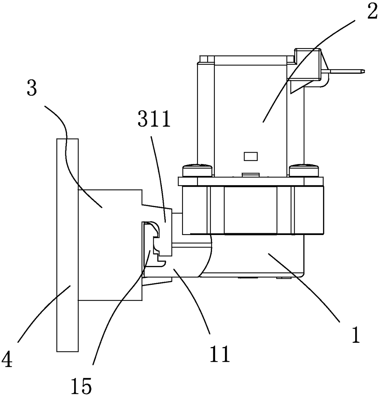
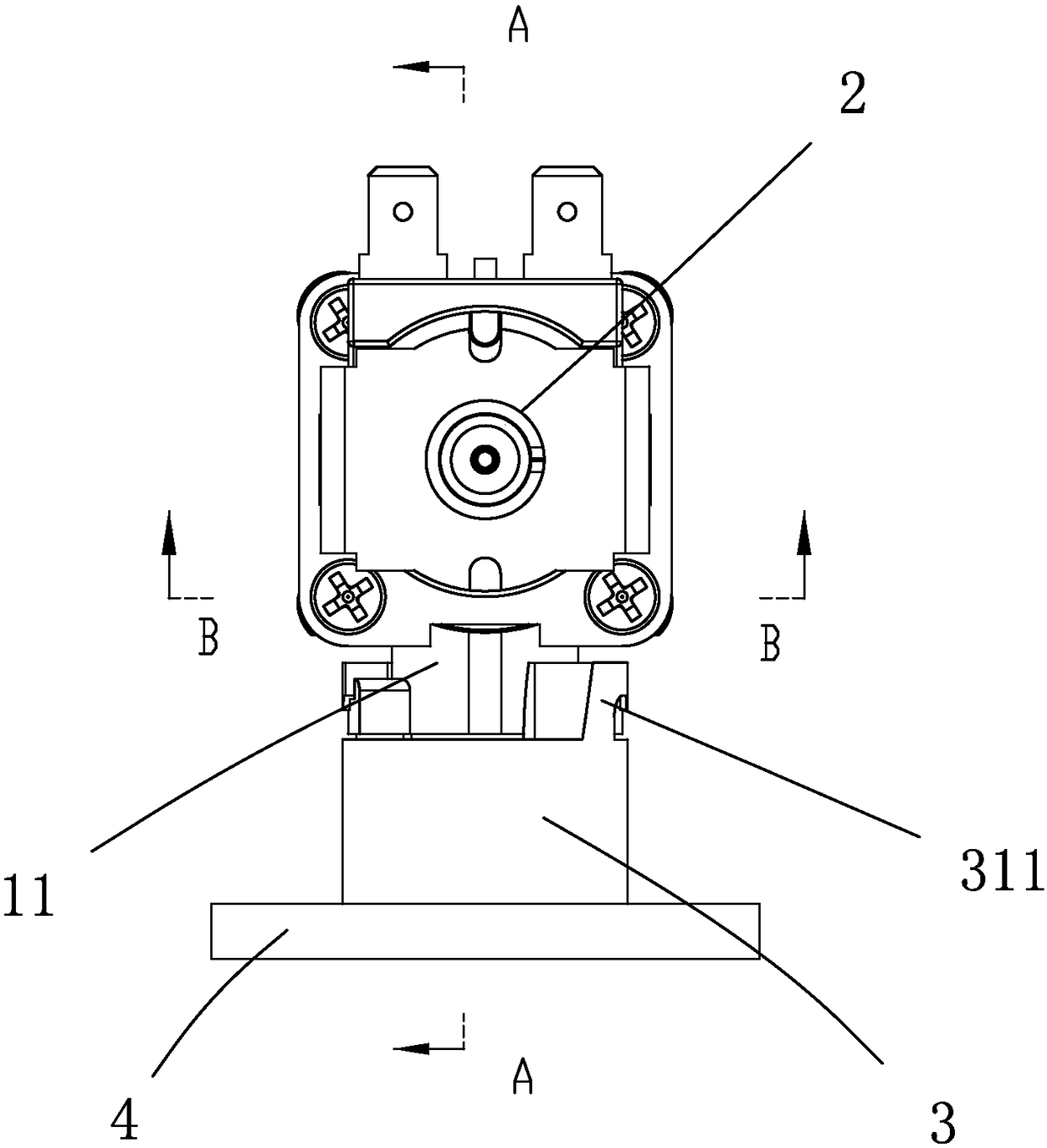
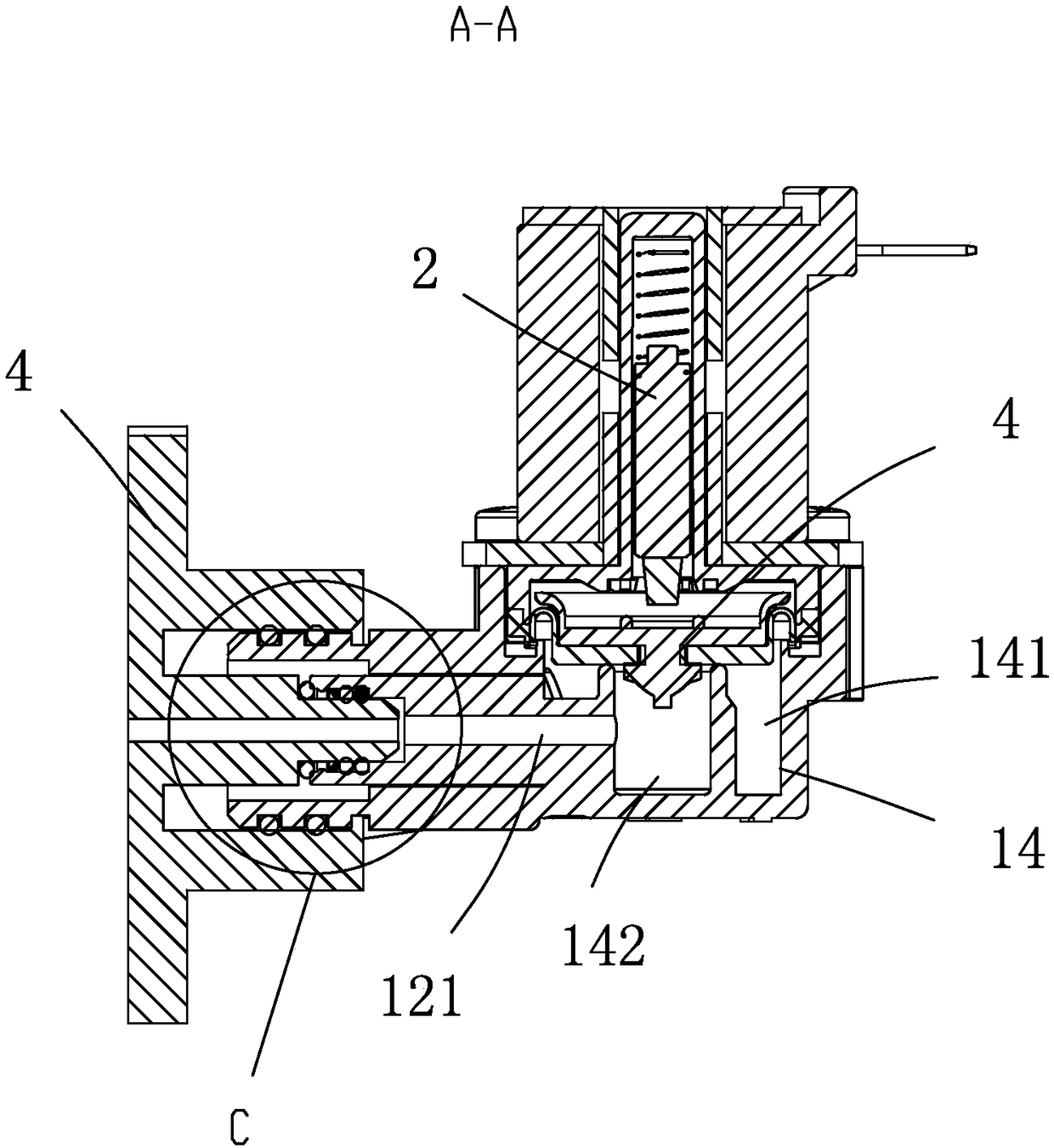
[0026] Embodiments of the connection structure between the solenoid valve and the water inlet and outlet pipelines of the present invention are as follows: Figures 1 to 10As shown: It includes a solenoid valve and an adapter that is detachably connected to the solenoid valve. The solenoid valve includes a valve body 1 and an electromagnetic drive mechanism 2 arranged on the valve body. The electromagnetic drive mechanism 2 generates driving force by using the principle of electromagnetic drive The direction of its driving force can be linear or rotary. The valve body 1 includes an inner cavity 14, and an annular water barrier 16 is arranged in the valve inner cavity 14, and the inner cavity 14 is divided into a water inlet cavity 141 and a water outlet cavity 142 by the water barrier wall 16. One end is provided with a valve port 161, with the valve port 161 as the boundary, the water inlet chamber 141 is arranged on the inner side of the water barrier 16, the water outlet ch...


PUM


Abstract

The invention discloses a connecting structure of an electromagnetic valve and a water in-out pipeline. The connecting structure comprises the electromagnetic valve and a switchover part, wherein theelectromagnetic valve comprises a valve body; the valve body comprises a cavity; a first water inlet pipe and a first water outlet pipe are arranged on the valve body; the first water outlet pipe is arranged at the inner hole of the first water inlet pipe; a first water inlet passage is formed between the outer wall of the first water outlet pipe and the inner wall of the first water inlet pipe; the inner hole of the first water outlet pipe forms a first water outlet passage; the switchover part comprises a base, a second water inlet pipe and a second water outlet pipe; the second water inletpipe and the second water outlet pipe are fixedly arranged on the base; a second water inlet passage is formed between the outer wall of the second water outlet pipe and the inner wall of the second water inlet pipe; and the inner hole of the second water outlet pipe forms a second water outlet passage. The connecting structure is simple, small and exquisite in size, small in occupied area, more convenient for butt joint with the water in-out pipeline and unlikely to be mounted reversely.

Description

technical field [0001] The invention relates to a connection structure between an electromagnetic valve and a water inlet and outlet pipeline. Background technique [0002] Solenoid valves are widely used in water purifiers, water dispensers, coffee machines, washing machines, dishwashers, solar water heaters, electric water heaters and other water appliances. According to the purpose, they include flow meter solenoid valves, water inlet solenoid valves, waste water solenoid valves, etc. . The solenoid valve generally includes a valve body and an electromagnetic drive mechanism connected to the valve body. The valve body includes an inner cavity, and the valve body is provided with a water inlet pipe and an outlet pipe communicated with the inner cavity of the valve body. In the prior art solenoid valve, the water inlet pipe and the water outlet pipe generally extend toward the opposite direction or the same side on both sides of the valve body. The water pipes are respect...

Claims


Application Information

Patent Timeline
IPC IPC(8): F16K27/00F16K11/00
CPCF16K19/00F16K27/00
Inventor 赵海杰赵彬宇王刚
Owner ZHEJIANG DAWEI ELECTRONICS
Why Eureka
Try Eureka