
Liquid crystal display panel and liquid crystal display device

A liquid crystal display panel and liquid crystal layer technology, which is applied in nonlinear optics, instruments, optics, etc., can solve the problems of high power consumption, poor display effect, and large eye damage of the display panel.

Active Publication Date: 2018-08-17
KUSN INFOVISION OPTOELECTRONICS
View PDF4 Cites 10 Cited by
  • Summary
  • Abstract
  • Description
  • Claims
  • Application Information

AI Technical Summary

Problems solved by technology

[0004] However, when the liquid crystal display panel works in the reflective mode in the above technology, the contrast ratio of the liquid crystal display panel is low, and the display effect is poor.
When working in the transmissive mode, the power consumption of the liquid crystal display panel is relatively high, and the damage to the eyes is greater

Method used


Image

  • Liquid crystal display panel and liquid crystal display device
  • Liquid crystal display panel and liquid crystal display device
  • Liquid crystal display panel and liquid crystal display device

Examples


Embodiment Construction

[0027] In order to further explain the technical means and effects of the present invention to achieve the intended purpose of the invention, the specific implementation, structure, features and effects of the present invention will be described in detail below in conjunction with the accompanying drawings and examples.

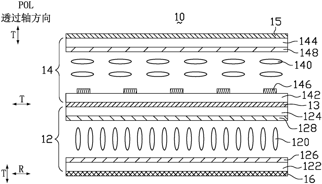
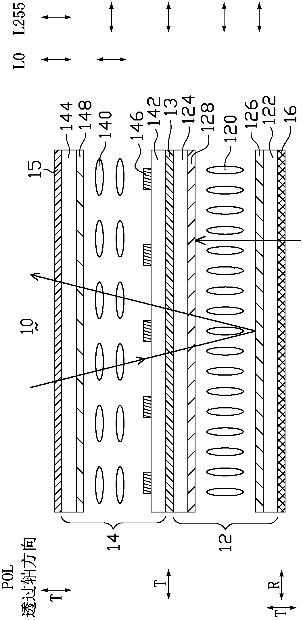
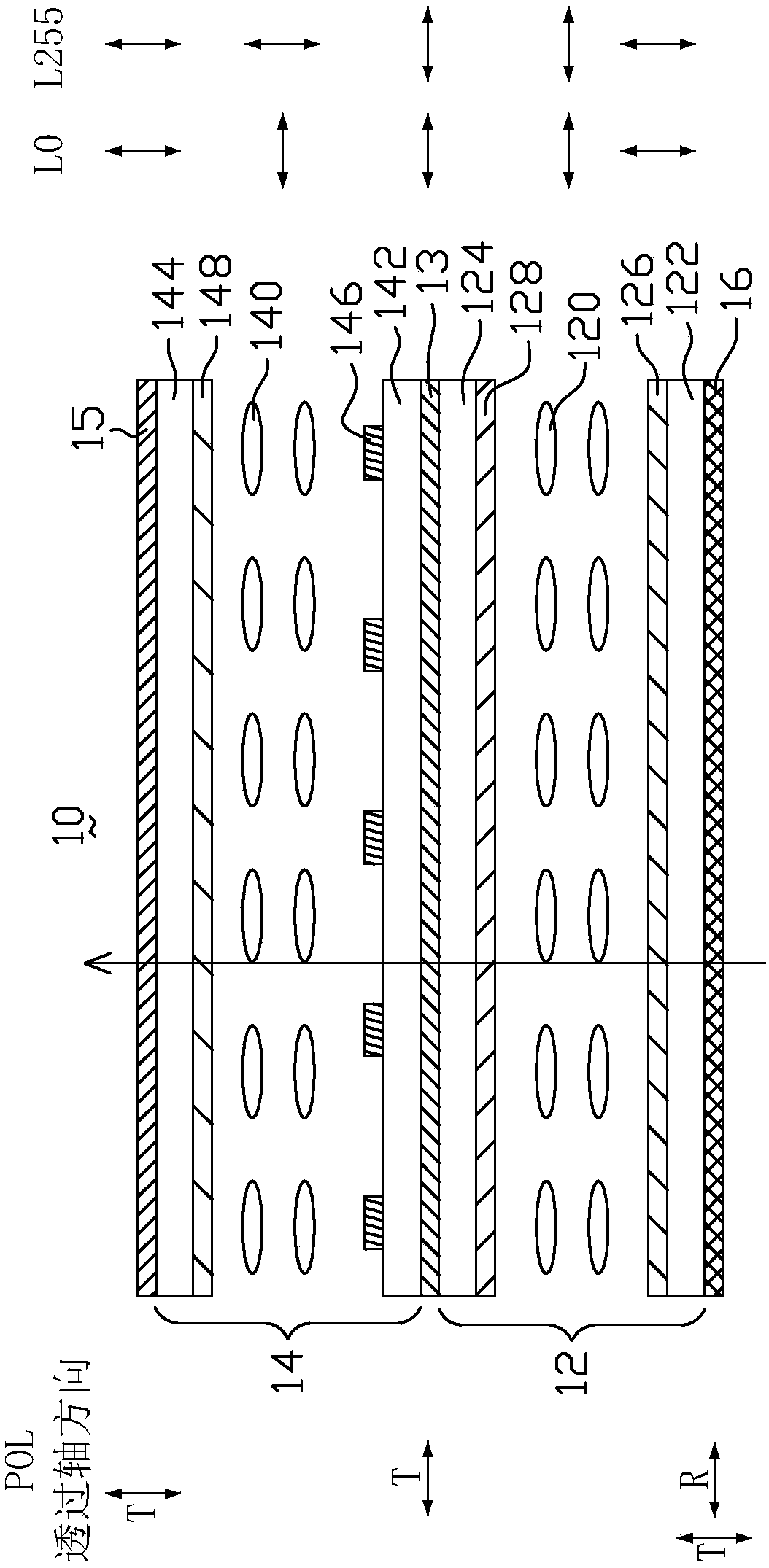
[0028] See figure 1 , which shows a schematic structural diagram of a liquid crystal display panel 10 in an embodiment of the present invention. A liquid crystal display panel 10 includes a backlight 20 , a selective reflection film 16 , a first liquid crystal cell 12 and a second liquid crystal cell 14 . The first liquid crystal cell 12 includes a first substrate 122 , a second substrate 124 and a first liquid crystal layer 120 disposed opposite to each other.

[0029] The second liquid crystal cell 14 is arranged opposite to the first liquid crystal cell 12 , and the second liquid crystal cell 14 is arranged above the first liquid crystal cell 12 in this em...


PUM


Abstract

The invention relates to a liquid crystal display panel. The liquid crystal display panel comprises a backlight source, a selective reflecting film, a first liquid crystal box and a second liquid crystal box, and the first liquid crystal box comprises a first substrate and a second substrate which are oppositely arranged and a first liquid crystal layer located between the first substrate and thesecond substrate; the second liquid crystal box comprises a third substrate and a fourth substrate which are oppositely arranged and a second liquid crystal layer located between the third substrate and the fourth substrate, the third substrate is arranged close to the second substrate, and the third substrate is arranged on the side, away from the first liquid crystal layer, of the second substrate; the selective reflecting film is used for reflecting the light incident from one side of the second liquid crystal box and transmitting the light emitted from the backlight source, wherein when liquid crystal molecules in the first liquid crystal layer lie flat, the liquid crystal display panel is in a transmission pattern, and when the liquid crystal molecules in the first liquid crystal layer stand, the liquid crystal display panel is in a reflection pattern. The invention further relates to a liquid crystal display device.

Description

technical field [0001] The invention relates to the technical field of liquid crystal display, in particular to a liquid crystal display panel and a liquid crystal display device. Background technique [0002] Liquid crystal display panels have the advantages of good picture quality, small size, light weight, low driving voltage, low power consumption, no radiation and relatively low manufacturing cost, and are widely used in electronic products such as notebook computers, mobile phones, e-books, and LCD TVs. in the device. [0003] In recent years, with the continuous development and promotion of liquid crystal display technology, the industry has developed a liquid crystal display panel that can be used in any environment, that is, a semi-reflective liquid crystal display device. The semi-reflective liquid crystal display device has two display modes: reflective mode and transmissive mode. When the ambient light is sufficient, the ambient light can be used to work in the ...

Claims


Application Information

Patent Timeline
IPC IPC(8): G02F1/1347G02F1/1335
CPCG02F1/133555G02F1/1347
Inventor 王新刚楚方方
Owner KUSN INFOVISION OPTOELECTRONICS
Learn More