
Stable electric power apparatus

A power device and stable technology, applied in the field of electric power, can solve the problems of power failure of electrical equipment, disconnection of plugs, unstable power supply connection, etc., and achieve the effects of convenient operation, stable automatic control and simple structure

Inactive Publication Date: 2018-08-17
广州弘唷网络科技有限公司
View PDF0 Cites 0 Cited by
  • Summary
  • Abstract
  • Description
  • Claims
  • Application Information

AI Technical Summary

Problems solved by technology

[0002] Nowadays, the energization of electrical equipment is mainly to insert the plug connected with the electrical equipment into the socket for matching connection. Although this matching connection method is simple to operate, the plug can still be pulled out directly. When the wire is connected with the electrical equipment, the plug will be disconnected from the matching connection, resulting in a sudden power failure of the electrical equipment. Therefore, the existing matching connection method has the risk of unstable power supply connection, which is easy to cause The equipment is damaged due to sudden power failure, and the existing matching connection method requires a large force to be applied when the plug is pulled out or inserted, and the operation is more laborious

Method used


Image

  • Stable electric power apparatus
  • Stable electric power apparatus
  • Stable electric power apparatus

Examples


Embodiment Construction

[0013] Combine below Figure 1-Figure 4 The present invention will be described in detail.

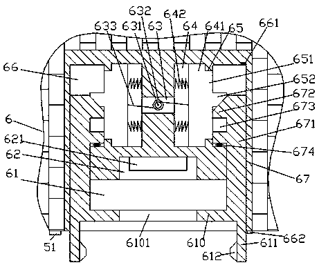
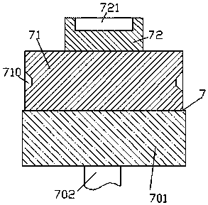
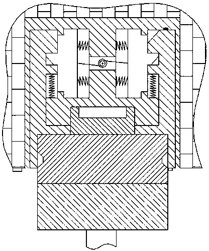
[0014] refer to Figure 1-Figure 4 , according to an embodiment of the present invention, a stable power device includes a wall 5, a power socket 6 fixed on the front surface of the wall 5, and a power plug 7 for mating connection with the power socket 6, the A slot 61 is provided in the front end surface of the power socket 6, and a first slide chamber 64 corresponding to the left and right is provided in the power socket 6 on the rear side of the slot 61. The interphase connection is provided with a connecting groove 63, the connecting groove 63 is fitted with a reel 631, and the bottom end of the reel 631 is connected with a motor 632 fixed in the inner wall of the bottom of the connecting groove 63 , the first sliding chamber 64 is smoothly fitted with a first sliding block 641 connected thereto, and the first sliding chamber 64 is provided with a second sliding chamber 66 on the...


PUM


Abstract

The invention discloses a stable electric power apparatus. The stable electric power apparatus comprises a wall, an electric power socket fixedly arranged in the front end plane of the wall, and an electric power plug matched and connected with the electric power socket; a slot is formed in the front side end plane of the electric power socket; first sliding cavities, corresponding left and right,are formed in the electric power socket on the back side of the slot; a connecting groove is connected between the two groups of first sliding cavities; a winding wheel is matched and connected in the connecting groove; the tail of the bottom of the winding wheel is in power connection with a motor which is fixedly arranged on the bottom inner wall of the connecting groove; a first sliding blockis smoothly matched and connected in each first sliding cavity; a second sliding cavity is formed in one side, back to the connecting groove, of each first sliding cavity; and a first run-through holeis formed between each second sliding cavity and the corresponding first sliding cavity.

Description

technical field [0001] The invention relates to the technical field of electric power, in particular to a stable electric power device. Background technique [0002] Nowadays, the energization of electrical equipment is mainly to insert the plug connected with the electrical equipment into the socket for matching connection. Although this matching connection method is simple to operate, the plug can still be pulled out directly. When the wire is connected with the electrical equipment, the plug will be disconnected from the matching connection, resulting in a sudden power failure of the electrical equipment. Therefore, the existing matching connection method has the risk of unstable power supply connection, which is easy to cause The equipment is damaged due to a sudden power failure, and the existing matching connection method requires a large force to be applied when the plug is pulled out or inserted, and the operation is relatively laborious. Contents of the invention ...

Claims


Application Information

Patent Timeline
Patent Type & Authority Applications(China)
IPC IPC(8): H01R13/44H01R13/502H01R13/627H01R13/629H01R13/703
CPCH01R13/44H01R13/502H01R13/6275H01R13/629H01R13/7035
Inventor 覃日雄
Owner 广州弘唷网络科技有限公司
Learn More