Indoor unit, motor waterproof structure of indoor unit and air conditioner

A technology of waterproof structure and indoor unit, applied in electromechanical devices, prevention of condensed water, electrical components, etc., can solve problems affecting safety performance, condensed water cannot be drained in time, motor burnout, etc., to improve safety performance and improve production Efficiency and quality reliability, the effect of preventing water from entering the motor

Pending Publication Date: 2018-08-17
ZHUHAI GREE REFRIGERATION TECH CENT OF ENERGY SAVING & ENVIRONMENTAL PROTECTION
View PDF0 Cites 6 Cited by
  • Summary
  • Abstract
  • Description
  • Claims
  • Application Information

AI Technical Summary

Problems solved by technology

[0005] Therefore, the technical problem to be solved by the present invention is to overcome the defect that the condensed water on the motor cover of the air-conditioning indoor unit in the prior art cannot be drained in time, causing the motor to burn out and affecting the safety performance, thereby providing a motor for the indoor unit. Waterproof structure, indoor unit and air conditioner

Method used


Image

  • Indoor unit, motor waterproof structure of indoor unit and air conditioner
  • Indoor unit, motor waterproof structure of indoor unit and air conditioner
  • Indoor unit, motor waterproof structure of indoor unit and air conditioner

Examples


Embodiment 1

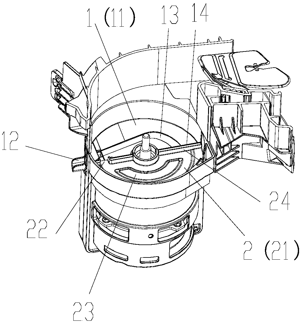
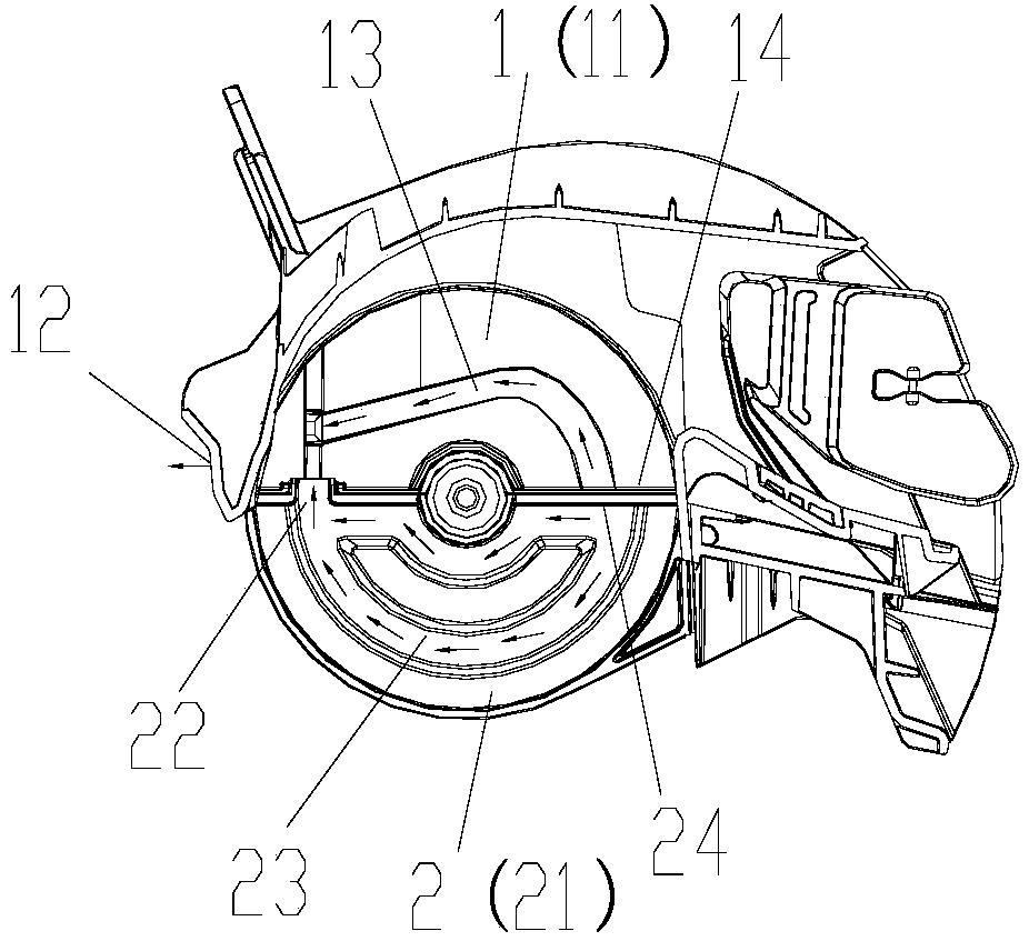
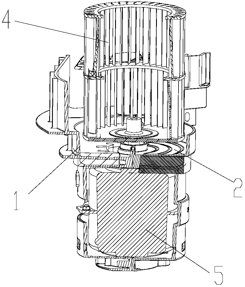
[0047] Such as Figure 1-5 As shown, the present invention provides a motor waterproof structure for an indoor unit, which includes an air duct bottom 1 and a motor cover 2, and the air duct bottom 1 is spliced ​​with the motor cover 2 to form a motor shaft 7 in between. The fan blade 4 is located above the bottom of the air duct 1 and the motor cover 2, and the fan blade 4 is connected to the motor shaft 7 and can be rotated by the motor shaft 7, and the motor 5 is located on the motor shaft 7. Below the bottom of the air duct 1 and the motor cover 2, and the motor shaft 7 is connected to the motor 5 and driven by the motor 5 (motor shaft 7) to the rotating part 1 and the motor cover 2,

[0048] The upper surface of the motor cover 2 forms a motor water receiving tank 21 capable of receiving condensed water, the upper surface of the air duct bottom 1 forms an air duct water receiving tank 11 capable of receiving condensed water, and the bottom surface of the motor water recei...

Embodiment 2

[0074] This embodiment is a further improvement made on the basis of Embodiment 1, as Figure 1-2 , 6 and 7, preferably, a first rib 24 protrudes upward at the position where the motor cover 2 is connected to the bottom 1 of the air duct, and is formed on the bottom 1 of the air duct. The position where the motor cover 2 is connected is also formed with a second rib 14 protruding upwards, and the first rib 24 and the second rib 14 are in close contact with each other.

[0075] By arranging the first rib protruding upward on the motor cover and the second rib protruding upward at the bottom of the air duct, and making the two closely fit, the distance between the motor cover and the bottom of the air duct can be improved. The sealing performance prevents condensation water or cold air from penetrating directly into the motor along the gap between the water receiving tray and the air duct, further preventing the occurrence of water ingress into the motor;

[0076] The drainage ...


PUM


Abstract

The invention provides an indoor unit, a motor waterproof structure of the indoor unit and an air conditioner. The motor waterproof structure comprises an air passage bottom (1) and a motor cover, a motor water receiving groove (21) capable of receiving condensate water is formed in the upper surface of the motor cover (2), and an air passage water receiving groove (11) is capable of receiving condensate water is formed in the upper surface of the air passage bottom (1). One side, close to the air passage water receiving groove (11), of the bottom face of the motor water receiving groove (21)is provided with a first water outlet (22). The first water outlet (22) extends towards the direction of the air passage water receiving groove (11) to a position above the bottom face of the air passage water receiving groove (11). By the motor waterproof structure, condensate water in the motor water receiving groove can be effectively discharged into the air passage water receiving groove, condensate water on the motor cover can be discharged timely to effectively solve the problem of drainage of condensate water in an air passage, safety improvement, structural simplicity and reliability in assembly are realized, and integral production efficiency and reliability are improved.

Description

technical field [0001] The invention belongs to the technical field of air conditioning, and in particular relates to a motor waterproof structure of an indoor unit, an indoor unit and an air conditioner. Background technique [0002] The internal unit of the air conditioner uses the evaporator for heat exchange. In the cooling mode, the indoor heat is transferred to the outside. The air duct part is in contact with the cold air for a long time during the cooling process, and at the same time its surroundings are in contact with the hot air for a long time. Condensation water will be generated on the outer or inner walls of parts where all the hot and cold air meet on the air duct. If the condensation water cannot be effectively and timely drained, it may flow to the live parts such as the motor, causing the motor to burn out and other quality problems. security incident. The drainage design of the existing internal through-flow circular cabinet machine is unreliable, and i...

Claims


Application Information

Patent Timeline
Patent Type & Authority Applications(China)
IPC IPC(8): H02K5/10F24F13/22
CPCH02K5/10F24F13/222
Inventor 余明养王振勇欧峥杨登明陈珠秀李颖颖孙小洪肖林辉陈荣华吴晓岳王高敏
Owner ZHUHAI GREE REFRIGERATION TECH CENT OF ENERGY SAVING & ENVIRONMENTAL PROTECTION
Why Eureka
Try Eureka