
Vibration screening machine

A technology of vibrating screening machine and vibrating mechanism, which is applied in the direction of screening, solid separation, grille, etc., can solve the problems of low screening efficiency, high price, unsatisfactory vibration effect, etc., and achieve the effect of improving the screening effect

Active Publication Date: 2018-08-21
长兴县悦林废旧物资回收有限公司
View PDF8 Cites 5 Cited by
  • Summary
  • Abstract
  • Description
  • Claims
  • Application Information

AI Technical Summary

Problems solved by technology

[0002] At present, the vibration effect of the equipment when separating and screening granular materials is not satisfactory, the screening efficiency is low, and the screening is extremely incomplete. The vibration equipment with multiple degrees of freedom is expensive and not suitable for the needs of ordinary screening and separation.

Method used


Image

  • Vibration screening machine
  • Vibration screening machine
  • Vibration screening machine

Examples


Embodiment Construction

[0026] The implementation of the present invention will be illustrated by specific specific examples below, and those skilled in the art can easily understand other advantages and effects of the present invention from the contents disclosed in this specification.

[0027] Below in conjunction with accompanying drawing and embodiment the present invention will be further described:

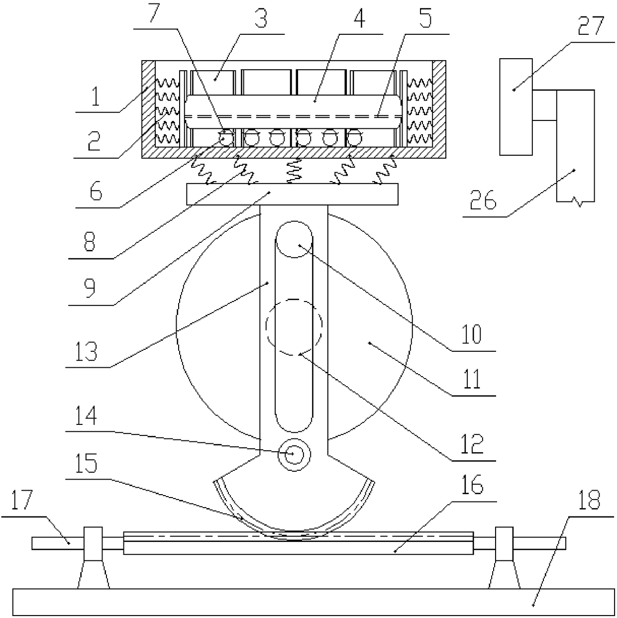
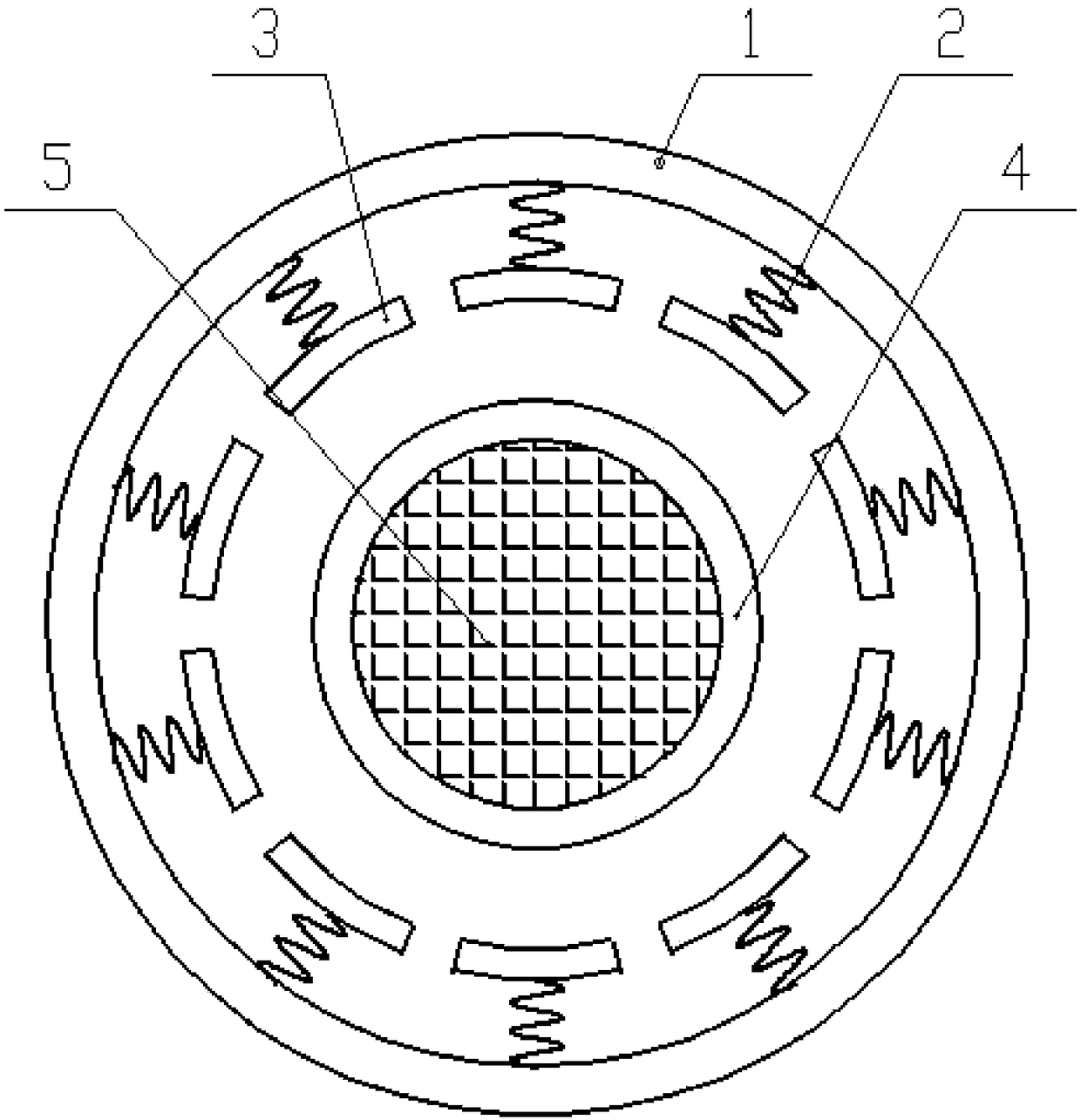
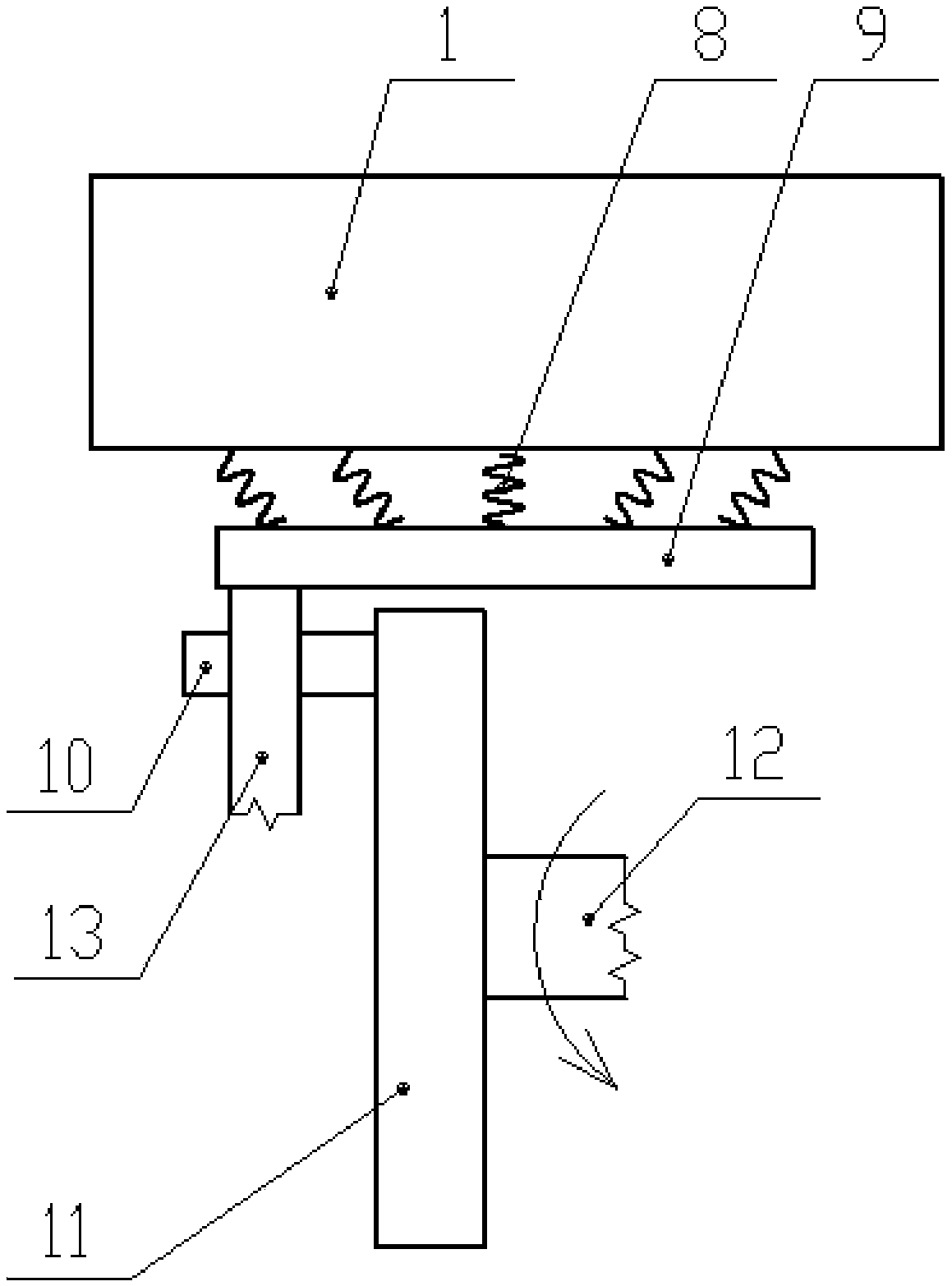
[0028] Such as figure 1 Shown in -3, a kind of vibrating screening machine comprises frame, screening parts, some vibrating springs 8 and vibrating mechanism sequentially from top to bottom.

[0029] The screening part includes a round frame 1 and an impact spring 2, a baffle plate 3, and a sieve plate part 4 located in the round frame 1; one end of the impact spring 2 is fixed on the inner wall of the round frame 1 along the radial direction of the round frame 1, and the other end is connected with the tile The circular arc outer walls of the sheet-shaped baffles 3 are connected. The baffles 3 ar...


PUM


Abstract

The invention discloses a vibration screening machine. Screening components comprises a round frame, a colliding spring, a baffle and a screening disc component, and the colliding spring, the baffle and the screening disc component are located in the round frame. One end of the colliding spring is fixed to the inner wall of the round frame in the radial direction of the round frame, and the baffleis arranged perpendicular to the bottom face in the round frame and can freely slide on the bottom face. A supporting plate is fixed to the upper end of a swing arm, and gear teeth of a gear are arranged on the arc edge of a lower end sector part. A colliding structure comprises an L-shaped rocker arm and a T-shaped movable rod, and a smooth cylinder is arranged at one end of the rocker arm. Thecylinder is detachably fixed into a strip-shaped groove in the rocker arm. The movable rod comprises a vertical rod section and a horizontal rod section. The vertical rod section is perpendicular to the middle of the horizontal rod section, and the vertical rod section is horizontally arranged and located in a pair of fixed guide blocks. A guide column on a rotary disc stretches into a strip-shaped penetrating hole. Sliding columns are arranged at the two ends of a gear rack, and the two sliding columns are located on shaft sleeves at the two ends of a base. The vibration screening machine isstable in structure, high in screening efficiency, good in effect and beneficial to use and popularization.

Description

technical field [0001] The invention belongs to the technical field of screening and separation, and in particular relates to a vibration screening machine. Background technique [0002] At present, the vibration effect of equipment for separating and screening granular materials is not satisfactory, the screening efficiency is low, and the screening is extremely incomplete. The vibration equipment with multiple degrees of freedom is expensive and not suitable for the needs of ordinary screening and separation. Contents of the invention [0003] The purpose of the present invention is to solve the above technical problems and provide a vibrating screening machine, which has a stable structure, high screening efficiency and good effect, and is conducive to popularization and use. [0004] Technical scheme of the present invention is as follows: [0005] A vibrating screening machine, which sequentially includes a frame, a screening component, several vibrating springs and ...

Claims


Application Information

Patent Timeline
IPC IPC(8): B07B1/42B07B1/28
CPCB07B1/28B07B1/42
Inventor 王华银
Owner 长兴县悦林废旧物资回收有限公司
Learn More