Plate continuous punching device

A technology of stamping device and plate, applied in the direction of feeding device, positioning device, storage device, etc., can solve the problems of simple, continuous and rapid production, low production efficiency, etc.

Inactive Publication Date: 2018-08-21
应金宝
View PDF7 Cites 5 Cited by
  • Summary
  • Abstract
  • Description
  • Claims
  • Application Information

AI Technical Summary

Problems solved by technology

However, the functions of the current stamping machines are too simple and the degree of automation is not high. It usually requires manual operation, which is time-consuming and labor-intensive. The workpiece needs multi-station continuous stamping, and there is no good and fast automatic loading and unloading device, and manual loading and unloading are required in the connection of each stamping process, resulting in high labor intensity and low production efficiency

Method used


Image

  • Plate continuous punching device
  • Plate continuous punching device
  • Plate continuous punching device

Examples


Embodiment Construction

[0015] The present invention will be described in further detail below in conjunction with the embodiments of the drawings.

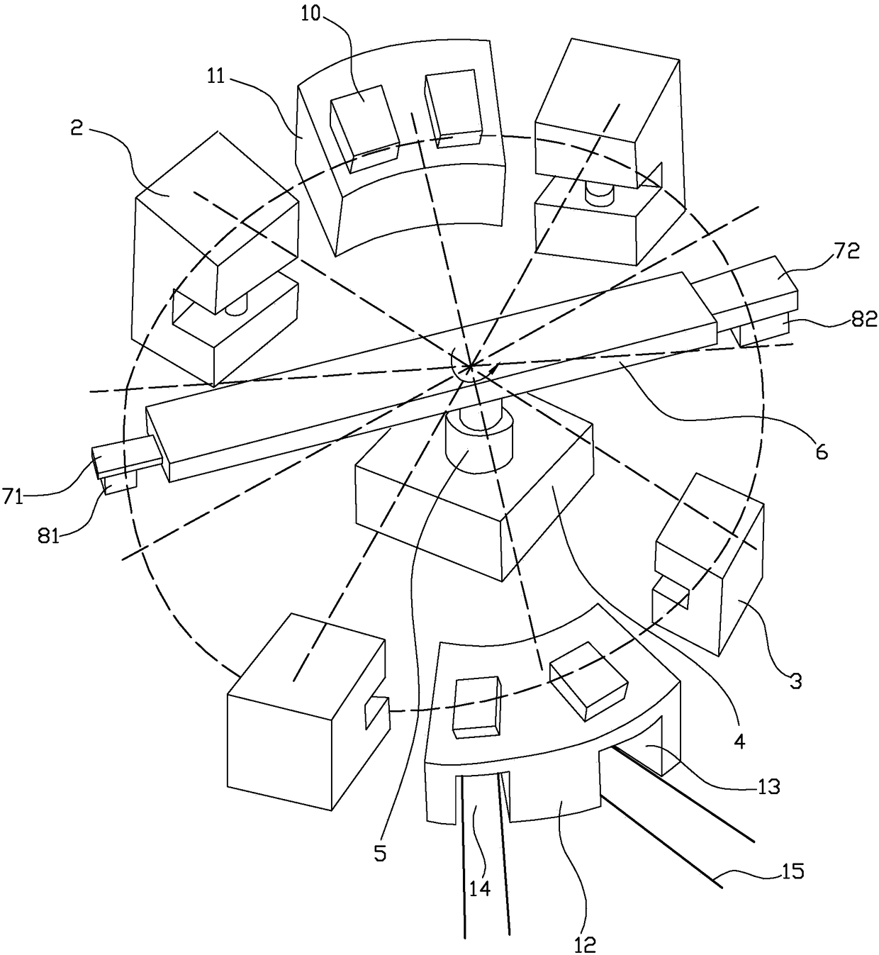
[0016] Such as Figure 1 to 3 As shown, the continuous stamping device of the plate in this embodiment includes a rotating batching assembly, a first material table 11, a second material table 12, a first stamping unit 2 and a second stamping unit 3.

[0017] Among them, the first material table 11, the second material table 12, the first press unit 2 and the second press unit 3 are arranged circumferentially outside the rotating batching assembly, and the first press unit 2 is formed by a plurality of presses arranged adjacently, The second press unit 3 is formed by multiple presses arranged adjacently. The number of presses of the second press unit 3 is the same as that of the first press unit 2. At the same time, the first material table 11 and the second material table 12 are arranged oppositely. The punching machines of the punching unit 2 are arranged...


PUM


Abstract

The invention discloses a plate continuous punching device. The plate continuous punching device is characterized by comprising a rotary burdening assembly, a first material table, a first punching unit, a second material table and a second punching unit are arranged on the exterior of the rotary burdening assembly in the circumferential direction, the first material table and the second materialtable are oppositely arranged and are provided with a feeding channel and a discharging channel in parallel, the bottoms of the feeding channel and the discharging channel are each provided with two parallel rails, and each rail is provided with a single vehicle; and the rotary burdening assembly comprises a base, a rotary cylinder vertically arranged above the base and a transverse beam transversely arranged at the output end of the rotary cylinder, a first sliding plate and a second sliding plate are arranged at the two ends of the transverse beam in a sliding manner, a first sucking deviceis arranged on the lower side face of the first sliding plate, and a second sucking device is arranged on the lower side face of the second sliding plate. As for multi-process punching plates, automatic continuous punching can be achieved, the labor intensity is reduced, and the punching efficiency is improved.

Description

Technical field [0001] The invention relates to the field of automatic stamping, in particular to a continuous stamping device for plate parts. Background technique [0002] Punching machines are commonly used industrial production equipment, especially equipment that is mainly used for stamping and shaping the end of slender materials such as profiles or steel pipes. However, the functions of the current punching machine are too simple and the degree of automation is not high. It usually requires manual operation, which is time-consuming and laborious. The quality of the punched products is poor and the production speed is slow. It cannot form a continuous and rapid production line, especially for one The workpiece needs to be continuously stamped in multiple stations, and there is no better and fast automatic loading and unloading device, and manual loading and unloading are required in the connection of various stamping processes, resulting in high labor intensity and low prod...

Claims


Application Information

Patent Timeline
IPC IPC(8): B21D43/02B21D43/14B21D43/18
CPCB21D43/027B21D43/14B21D43/18
Inventor 应金宝
Owner 应金宝
Why Eureka
Try Eureka