Transfer trolley for parts of small automobile

A small car and parts technology, applied in the field of auto parts, can solve the problems of large storage space, low labor efficiency, inconvenient transfer, etc., and achieve the effect of reducing storage space, convenient handling and transfer, and improving utilization rate

Active Publication Date: 2018-08-21
阳信创棣智能科技有限公司
View PDF6 Cites 3 Cited by
  • Summary
  • Abstract
  • Description
  • Claims
  • Application Information

AI Technical Summary

Problems solved by technology

[0002] Automobiles have tens of thousands of parts. In the production process of auto parts, if we only rely on manual transfer of the produced parts, it will not only consume a lot of labor but also have low work efficiency; in today's auto parts production plants It is common to see a kind of trolley used for transferring auto parts. Although this kind of trolley has a simple structure and can also transfer auto parts, the space it can place is limited due to the fixed position of the panel. To a certain extent, the space for placing the trolley is not fully utilized; the traditional transfer trolley is not only inconvenient for its own transfer due to the fixed setting of the overall frame, but also takes up a lot of storage space when it is not in use, so now there is a need for a small Auto parts transfer trolley, this kind of trolley is driven by electricity, which greatly reduces the burden on workers. The trolley is assembled as a whole by disassembled movable connection. It is equipped with a manual position adjustment device to make the placement of the panel according to its needs. The size of the transferred parts is adjusted and fixed, which greatly improves the utilization rate of the space of the trolley. When the trolley is not in use, it can be folded into a box shape, which is not only convenient for the overall handling and transfer of the trolley, but also greatly reduces its cost. required storage space

Method used


Image

  • Transfer trolley for parts of small automobile
  • Transfer trolley for parts of small automobile
  • Transfer trolley for parts of small automobile

Examples


Embodiment Construction

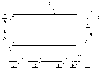
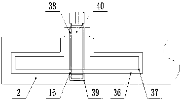
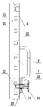
[0021] The present invention is specifically described below in conjunction with accompanying drawing, as Figure 1-5Shown, a kind of trolley that is used for small auto parts transfer, comprises cart frame 1, and described cart frame 1 is respectively provided with driving wheel 3, base frame 1 by base rectangular base 2, the two sides below the front end of base rectangle base 2 respectively. The universal wheels 4 provided on both sides below the rear end of the rectangular base 2 and the push handle 5 provided at the rear end of the basic rectangular base 2 are composed of the upper end of the rear side of the basic rectangular base 2 and along its left and right width. The push-down hand frame 6 provided with fixed direction, the push-up hand frame 7 provided above the push-down hand frame 6, the push rods 8 hinged respectively on both sides of the top of the push-up hand frame 7, the push-up hand frame 7 and the rear end surface of the push-down hand frame 6 One end of t...


PUM


Abstract

The invention discloses a transfer trolley for parts of a small automobile. The transfer trolley includes a trolley frame. The trolley frame is composed of a basic rectangular base, a driving wheel, auniversal wheel and a pushing hand. The pushing hand is composed of a lower pushing hand frame, an upper pushing hand frame, a push rod and an arched connecting frame. Vertical supporting columns arearranged on the two sides of the upper portion of the front end of the basic rectangular base, vertical supporting frames are hinged to the top ends of the basic rectangular base respectively, a placing panel is arranged between the vertical supporting frames located on the two sides and the upper pushing hand frame, and a manual position adjustment device is disposed in an inner chamber of the placing panel and composed of an elongated positioning groove, a first returning spring, a positioning pin, a circular through groove, a fixed bearing, a rotating shaft, a winding wheel, a torsion spring, a steel wire and a small rotating frame. The transfer trolley has the advantages of being simple in structure and high in practicality.

Description

technical field [0001] The invention relates to the field of auto parts, in particular to a transfer trolley for small auto parts. Background technique [0002] Automobiles have tens of thousands of parts. In the production process of auto parts, if we only rely on manual transfer of the produced parts, it will not only consume a lot of labor but also have low work efficiency; in today's auto parts production plants It is common to see a kind of trolley used for transferring auto parts. Although this kind of trolley has a simple structure and can also transfer auto parts, the space it can place is limited due to the fixed position of the panel. To a certain extent, the space for placing the trolley is not fully utilized; the traditional transfer trolley is not only inconvenient for its own transfer due to the fixed setting of the overall frame, but also takes up a lot of storage space when it is not in use, so now there is a need for a small Auto parts transfer trolley, thi...

Claims


Application Information

Patent Timeline
Patent Type & Authority Applications(China)
IPC IPC(8): B62B3/02B62B5/00
CPCB62B3/02B62B5/0033B62B5/0053B62B2205/006B62B2205/04B62B2205/30
Inventor 王健
Owner 阳信创棣智能科技有限公司
Why Eureka
Try Eureka