Fiber grating sensor package structure and packaging method suitable for high-temperature environment

A fiber grating and packaging structure technology, applied in the field of sensors, can solve the problems of fiber grating sensor performance influence, inaccurate measurement results, poor bonding effect, etc., and achieve the effects of simple packaging, simple operation, and convenient bonding and installation.

Active Publication Date: 2018-08-21
HARBIN INST OF TECH
View PDF5 Cites 3 Cited by
  • Summary
  • Abstract
  • Description
  • Claims
  • Application Information

AI Technical Summary

Problems solved by technology

[0003] At present, there are two commonly used packaging methods. One is to glue the fiber grating into the protective part, and then glue the protective part to the test part. When in use, the strain of the test part is transmitted to the fiber grating through the protective part. sensor, but in this process, the problem of strain transmission will make the measurement results inaccurate. The other is to directly bond the fiber grating to the object under test as a whole, but this method is used in a high temperature (above 1000°C) environment In this case, it is necessary to coat the sensing area (grating) of the fiber grating sensor with an adhesive. The adhesive may expand during use, which will not only affect the performance of the fiber grating sensor, but also The process is more difficult, usually the bonding effect is not good

Method used


Image

  • Fiber grating sensor package structure and packaging method suitable for high-temperature environment
  • Fiber grating sensor package structure and packaging method suitable for high-temperature environment
  • Fiber grating sensor package structure and packaging method suitable for high-temperature environment

Examples


Embodiment 1

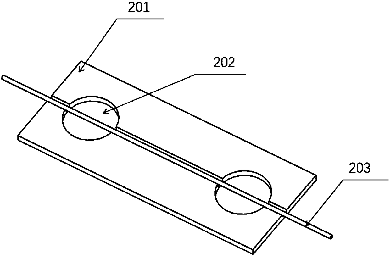
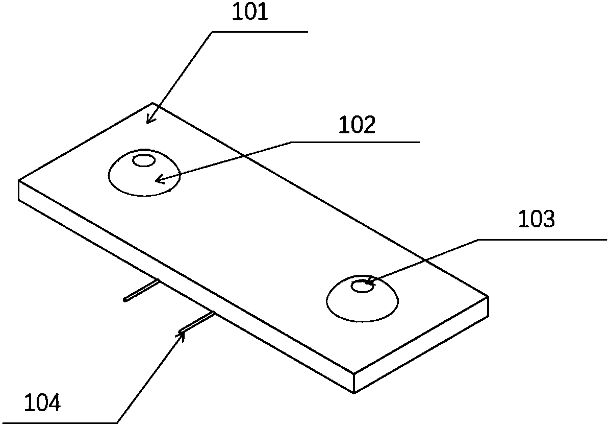
[0046] Such as Figure 1 to Figure 4 As shown, a fiber grating sensor packaging structure suitable for high-temperature environments provided by the embodiment of the present invention includes an upper package 101 and a lower package 201, and the lower package 201 is provided with two optical fiber fixing through holes 202 arranged at intervals for utilizing The high temperature adhesive fixes the fiber grating sensor 203 on the object under test. Preferably, the high-temperature adhesive can be selected from Resbond 989FS, 940HT Powder or other similar products.

[0047]The lower package 201 is also provided with an optical fiber placement part, which passes through two optical fiber fixing through holes and is divided into a first placement part, a second placement part and a third placement part by the two fiber fixing through holes 202. The placement part is located between the two optical fiber fixing through holes, and is used to place the sensing area of ​​the fiber g...

Embodiment 2

[0061] Such as Figure 5 As shown, the second embodiment is basically the same as the first embodiment, except that the second placement part and the third placement part are both grooves, and the first placement part is a long hole structure, that is, two optical fiber fixing through holes 202 To ensure that the sensing area of ​​the fiber grating sensor 203 is neither in contact with the upper package 101 nor with the lower package 201 . Due to the high viscosity of the high-temperature adhesive, the high-temperature adhesive will not flow into the sensing area of ​​the FBG sensor 203 even if it is connected between the two optical fiber fixing through holes 202 , and the performance of the FBG sensor 203 will not be affected.

Embodiment 3

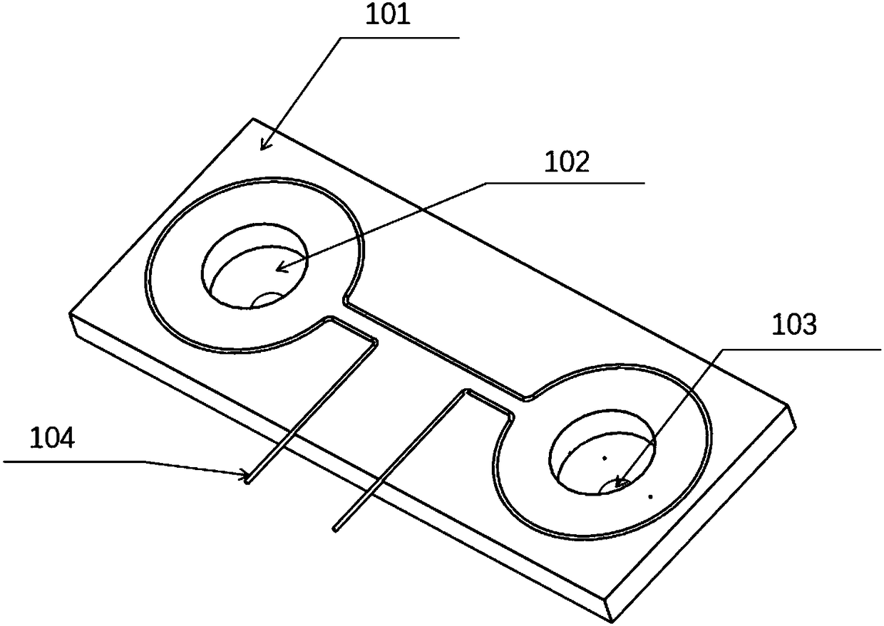
[0063] Such as Figures 6 to 11 As shown, this embodiment also provides a fiber grating sensor packaging structure suitable for high-temperature environments. The third embodiment is basically the same as the first embodiment, and the similarities will not be repeated. The differences are:

[0064] Specifically in this embodiment, the lower package 201 is a flat rectangular parallelepiped, and the two optical fiber fixing through-holes 202 arranged at intervals on the lower package 201 are tapered holes with a small opening at the top and a large opening at the bottom. Preferably, the cavity inside the optical fiber fixing through hole 202 is in the shape of an inverted bowl.

[0065] The structure of the upper package 101 is thinner than that of the lower package 201. The interior of the two injection holes 103 on the upper package 101 is funnel-shaped, that is, a tapered hole with a large opening at the top and a small opening at the bottom. Bottom protruding downwards (eg ...


PUM


Abstract

The invention relates to a fiber grating sensor package structure suitable for a high-temperature environment. The fiber grating sensor package structure comprises an upper layer package and a lower layer package; the lower layer package is provided with an optical fiber placement portion; two optical fiber fixing through holes which are spaced apart are formed in the lower layer package; the optical fiber placement portion is divided into a first placement portion, a second placement portion, and a third placement portion through the optical fiber fixing through holes; the first placement portion is located between the two optical fiber fixing through holes; the groove depth of the first placement portion is greater than the groove depths of the second placement portion and the third placement portion; the upper layer package includes two adhesive injection portions; the two adhesive injection portions are respectively corresponding to the two optical fiber fixing through holes; and adhesive injection holes are formed in the tops of the adhesive injection portions. The invention also provides a fiber grating sensor packaging method suitable for a high-temperature environment. Whenthe package structure of the invention is installed, a fiber grating sensor is directly bonded to a device to be tested, and therefore, measurement error caused by the problem of strain transmissioncan be avoided; and a two-point type bonding method is adopted, and therefore, the influence of an adhesive on the performance of the fiber grating sensor can be avoided.

Description

technical field [0001] The invention relates to the technical field of sensors, in particular to a fiber grating sensor packaging structure and packaging method. Background technique [0002] Fiber grating sensors have been widely used in military, aerospace, environmental monitoring and safety detection of civil building structures. In order to meet the requirements of various harsh environments, it is necessary to design a protective packaging structure for the fiber grating. [0003] At present, there are two commonly used packaging methods. One is to glue the fiber grating into the protective part, and then glue the protective part to the test part. When in use, the strain of the test part is transmitted to the fiber grating through the protective part. sensor, but in this process, the problem of strain transmission will make the measurement results inaccurate. The other is to directly bond the fiber grating to the object under test as a whole, but this method is used i...

Claims


Application Information

Patent Timeline
Patent Type & Authority Applications(China)
IPC IPC(8): G01D5/26
CPCG01D5/264G01D5/268
Inventor 解维华张双全孟松鹤易法军金华许承海李金平方国东
Owner HARBIN INST OF TECH
Why Eureka
Try Eureka