
Test system and terminal

A test system and terminal technology, which is applied in the electronic field, can solve problems such as error, power jump, and solder resistance that cannot be ignored, so as to ensure normal operation and improve the accuracy of power calculation.

Active Publication Date: 2018-08-21
浙江万物工场智能科技有限公司
View PDF16 Cites 0 Cited by
  • Summary
  • Abstract
  • Description
  • Claims
  • Application Information

AI Technical Summary

Problems solved by technology

However, the resistance value of the power calibration resistor is small, the resistance of the solder cannot be ignored, and there are tolerances in the power calibration resistor at the factory. It is not accurate enough, the battery jumps, even when the battery is not exhausted, the software will judge to shut down

Method used


Image

  • Test system and terminal

Examples


Embodiment Construction

[0018] In order to make the purpose, technical solutions and advantages of the embodiments of the present invention more clear, the following will describe each embodiment of the present invention in detail with reference to the accompanying drawings. However, those of ordinary skill in the art can understand that, in each implementation manner of the present invention, many technical details are provided for readers to better understand the present application. However, even without these technical details and various changes and modifications based on the following implementation modes, the technical solution claimed in this application can also be realized.

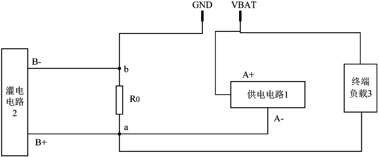
[0019] The first embodiment of the present invention relates to a test system, such as figure 1 As shown, it includes: a processor (not shown in the figure), a power supply circuit 1 and a power feeding circuit 2 . The test system in this embodiment is used for terminals, and the terminals can be portable resistance d...


PUM


Abstract

The embodiments of the present invention belong to the electronic technological field and disclose a test system and a terminal. According to the embodiments of the present invention, the test systemincludes a processor, a power supply circuit, and a power filling circuit; the output end of the power supply circuit is connected with the power source input end of the terminal; the input end of thepower supply circuit is connected with the first end of the power quantity calibration resistor of the terminal; the output end of the power filling circuit is connected with the first end of the power quantity calibration resistor; the input end of the power filling circuit is connected with the second end of the power quantity calibration resistor; the second end of the power quantity calibration resistor is grounded; the processor is in communication connection with the terminal; and the processor is used for controlling current at the power quantity calibration resistor which is detectedby the terminal, acquiring current calibration parameters according to the current at the power quantity calibration resistor which is detected by the terminal, the pre-stored output voltage of the power filling circuit, and the resistance value of the power quantity calibration resistor, and inputting the current calibration parameters to the terminal. Thus, the terminal can obtain an accurate current value according to the current calibration parameters, and the accuracy of power quantity calculation can be effectively improved.

Description

technical field [0001] The embodiments of the present invention relate to the field of electronic technology, and in particular to a test system and a terminal. Background technique [0002] With the improvement of hardware performance and the reduction of price, consumer electronic products have become more and more popular. For the sake of portability, mobile terminals such as smartphones, cameras, and tablet computers are equipped with batteries so that they can be used without an external power source. The battery is typically a lithium-ion battery with a high energy density. In order to avoid the inconvenience caused to users by power depletion, these devices generally provide a power estimation function. For example, the operating system of a smart phone can provide the user with information on the remaining battery power displayed in percentage, so that the user can charge it in time when the power is low. [0003] However, the inventors of this patent application h...

Claims


Application Information

Patent Timeline
IPC IPC(8): G01R1/04G01R35/00
CPCG01R1/04G01R35/00
Inventor 洪帆罗绿梅李玲刘雄
Owner 浙江万物工场智能科技有限公司
Learn More