
A tracking control method for hypersonic vehicle based on nonlinear function

A non-linear function and hypersonic technology, applied in the direction of adaptive control, general control system, control/regulation system, etc., can solve the problems of complex control model and poor robustness, and achieve strong robustness and improved control accuracy Effect

Active Publication Date: 2021-06-29
HARBIN INST OF TECH
View PDF5 Cites 0 Cited by
  • Summary
  • Abstract
  • Description
  • Claims
  • Application Information

AI Technical Summary

Problems solved by technology

[0004] The purpose of the present invention is to solve the problems of complex control models and poor robustness of existing aircraft, and propose a tracking control method for hypersonic aircraft based on nonlinear functions

Method used


Image

  • A tracking control method for hypersonic vehicle based on nonlinear function
  • A tracking control method for hypersonic vehicle based on nonlinear function
  • A tracking control method for hypersonic vehicle based on nonlinear function

Examples


specific Embodiment approach 1

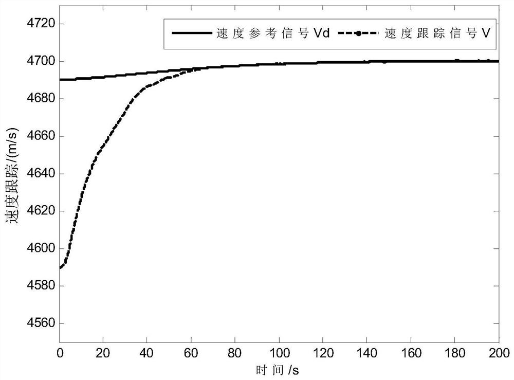
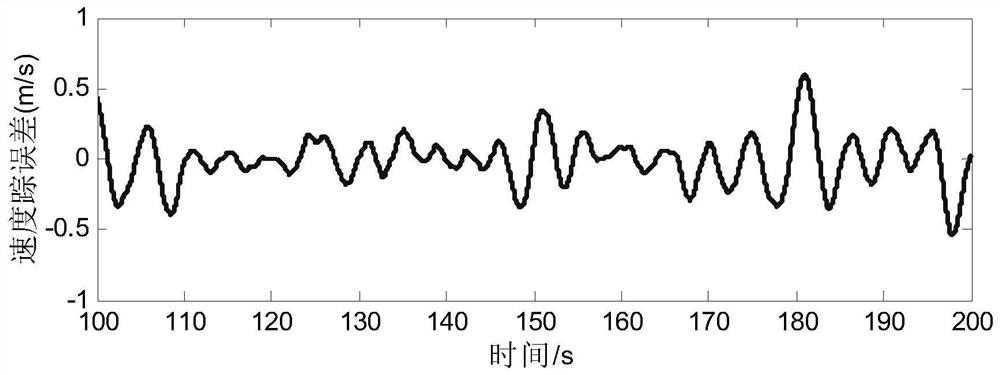
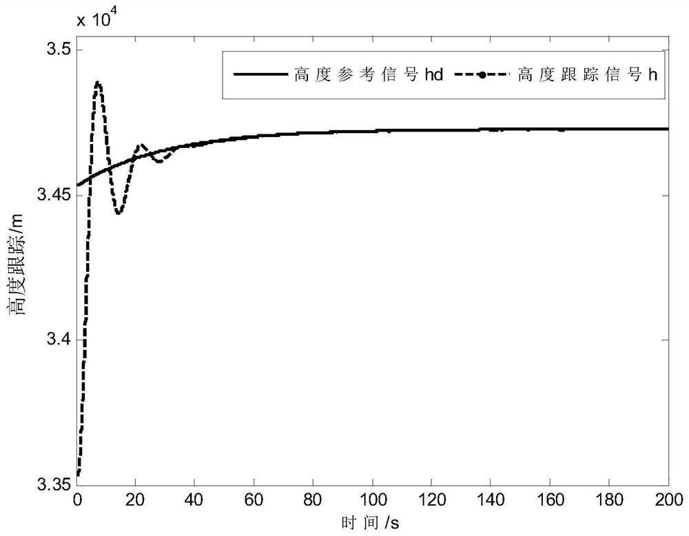
[0047] Specific embodiment one: a hypersonic vehicle tracking control method based on a nonlinear function comprises the following steps:

[0048] Hypersonic Vehicle Model Description

[0049] In order to facilitate the design of hypersonic vehicle control system, the feedback linearization model (Sun H, Li S, Sun C. Finite time integral sliding mode control of hypersonic vehicles [J]. Nonlinear Dynamics, 2013, 73 (1-2): 229-244.):

[0050]

[0051] where φ c and δ e is the control input, f v , f h , b 11 , b 12 , b 21 and b 22 For specific definitions, see literature (Sun H, Li S, Sun C. Finite time integral sliding mode control of hypersonic vehicles [J]. Nonlinear Dynamics, 2013, 73(1-2): 229-244.).

[0052] remember Then formula (1) can be rewritten as:

[0053]

[0054] Among them, Δf v , Δf h , Δb 11 , Δb 12 , Δb 21 , Δb 22 is a bounded term resulting from parameter uncertainty and external disturbances. Let Δ 1 =Δf V +Δb 11 δ e +Δb 12 φ c ...

specific Embodiment approach 2

[0170] Embodiment 2: The difference between this embodiment and Embodiment 1 is that in the step 1, the hypersonic vehicle model is converted through the state feedback controller, and the specific process of obtaining the transformed hypersonic vehicle model is as follows:

[0171] The hypersonic vehicle model is:

[0172]

[0173] in for σ 1 derivative of for σ 2 derivative of σ 1 and σ 2 is a function with the speed error and height error of the hypersonic vehicle as independent variables, d is the system (hypersonic vehicle model) disturbance, u is the control input, B is the control gain matrix, and F is the intermediate function;

[0174]

[0175]

[0176] B=-b

[0177]

[0178] in is the third derivative of the reference speed signal, is the fourth derivative of the reference height, f V is a nonlinear function with the speed of the hypersonic vehicle as an independent variable, f h is a nonlinear function with the height of the hypersonic vehi...

specific Embodiment approach 3

[0184] Specific implementation mode three: the difference between this implementation mode and specific implementation mode one or two is: the expression of s in the said step two is:

[0185] s = σ 2 +k 2 σ 1

[0186] Other steps and parameters are the same as those in Embodiment 1 or Embodiment 2.


PUM


Abstract

A tracking control method for a hypersonic vehicle based on a nonlinear function, and the invention relates to a tracking control method for a hypersonic vehicle based on a nonlinear function. The invention aims to solve the problems of complex control models and poor robustness of existing aircraft. The present invention includes: step 1: transforming the hypersonic vehicle model through a state feedback controller to obtain a transformed hypersonic vehicle model; step 2: designing an adaptive nonlinear model according to the transformed hypersonic vehicle model obtained in step 1 Robust controller u 0 . The invention provides that on the basis of the input-output linearization model, it is transformed into a general multi-variable second-order system by introducing auxiliary error variables. Aiming at the unknown upper bound of system disturbance, a nonlinear robust controller is designed by introducing a new continuously differentiable nonlinear saturation function, combined with adaptive theory. The invention is used in the field of aircraft.

Description

technical field [0001] The invention relates to a hypersonic vehicle tracking control method based on a nonlinear function. Background technique [0002] Hypersonic vehicles are highly forward-looking, strategic and driving, and have shown great development potential in both military and civilian aspects, so they have become a hot spot for research and development in various countries. Compared with conventional aircraft, hypersonic aircraft adopts a unique fuselage-engine integrated design, resulting in complex characteristics such as strong nonlinearity, strong coupling, and fast time-varying during flight, making the closed-loop control system of hypersonic aircraft robust. The device design faces many challenges. [0003] In recent years, a variety of control theories have been applied to the design of hypersonic vehicle controllers. Based on the control model, they are mainly divided into linearization-based models and nonlinear-based models. Literature (Sigthorsson D...

Claims


Application Information

Patent Timeline
Patent Type & Authority Patents(China)
IPC IPC(8): G05B13/04
CPCG05B13/042
Inventor 宋申民孙经广王岩谭立国于志刚
Owner HARBIN INST OF TECH
Learn More