
Anti-theft power distribution cabinet with buffer protection function

A protection function and anti-theft technology, which is applied in substation/power distribution device housing, electrical components, substation/switch layout details, etc., can solve the problems of power cabinet heat dissipation, unstable working status, poor anti-theft effect, etc., to improve The uniformity of heat dissipation, the improvement of protection effect, and the effect of good heat dissipation

Inactive Publication Date: 2018-08-21
韩银兰
View PDF3 Cites 2 Cited by
  • Summary
  • Abstract
  • Description
  • Claims
  • Application Information

AI Technical Summary

Problems solved by technology

The current heat dissipation devices generally rely on heat dissipation holes for heat dissipation. In order to prevent foreign objects from falling into the power distribution cabinet from the top plate, the aperture and number of heat dissipation holes on the top plate are limited, which will lead to slow heat dissipation and make the power The heat of the power distribution cabinet is always in a state of accumulation, which affects the components inside the power distribution cabinet and makes the working state unstable, and the heat dissipation of the power distribution cabinet is not enough to dissipate the heat in the power cabinet; the existing The anti-theft effect of the power distribution cabinet is poor, and equipment is often stolen; when the power distribution cabinet is working, it will vibrate, the power distribution cabinet is rigidly connected, and the components in the power distribution cabinet are also rigidly connected. Long-term vibration will bury hidden dangers for accidents

Method used


Image

  • Anti-theft power distribution cabinet with buffer protection function
  • Anti-theft power distribution cabinet with buffer protection function

Examples


Embodiment Construction

[0022] The embodiments of the present invention will be described in detail below with reference to the accompanying drawings, but the present invention can be implemented in various ways defined and covered by the claims.

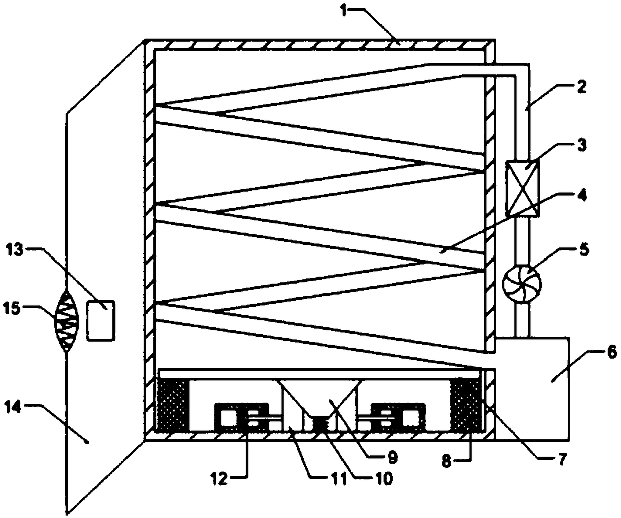
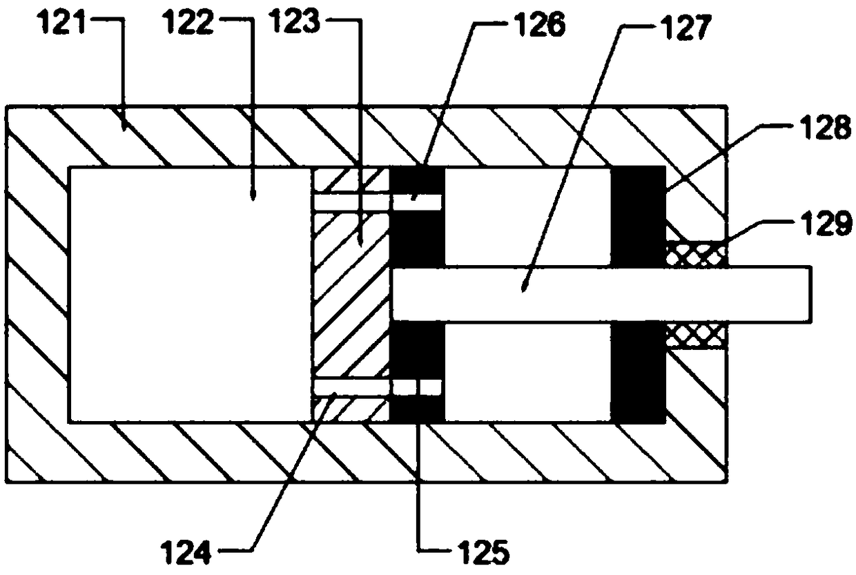
[0023] see Figure 1-Figure 2 , in this embodiment, an anti-theft power distribution cabinet with a buffer protection function, including a cabinet body 1, the inner bottom of the cabinet body 1 is provided with a mounting plate 7, the lower side of the mounting plate 7 and the inner bottom of the cabinet body 1 The first guide block 9 is fixedly connected to the middle of the lower side of the installation plate 7. The cross section of the first guide block 9 is isosceles trapezoidal. A second guide block 11, the cross section of the second guide block 11 is a right-angled trapezoid, and the slope of the second guide block 11 is in contact with the slope of the first guide block 9, and one side of the second guide block 11 is connected with a buffer devic...


PUM


Abstract

The invention provides an anti-theft power distribution cabinet with a buffer protection function. The anti-theft power distribution cabinet comprises a cabinet body, a mounting plate is arranged at the bottom of the interior of the cabinet body, and the lower side of the mounting plate is connected with the bottom of the interior of the cabinet body through a damping rubber pad. A first guiding block is fixedly connected to the middle of the lower side of the mounting plate, the cross section of the first guiding block is in an isosceles trapezoid shape, two second guiding blocks are disposedunder the first guiding block, the cross section of each second guiding block is in a right-angled trapezoid shape, and the inclined surfaces of the second guiding blocks are in contact with the inclined surfaces of the first guiding block. A buffering device is connected to one side of each second guiding block. The anti-theft power distribution cabinet has the advantages that the first guidingblock moves downward, the second guiding blocks matched with the first guiding block move to both sides, correspondingly a buffering column drives a moving plate to move, the moving plate to extrudeshydraulic oil, and the hydraulic oil slowly flows out through first through holes, so that the moving speed of the moving plate is greatly decreased, and a certain buffering effect is achieved.

Description

technical field [0001] The invention relates to the technical field of power distribution cabinets, in particular to an anti-theft power distribution cabinet with a buffer protection function. Background technique [0002] Power distribution cabinets are divided into power distribution cabinets, lighting distribution cabinets, and metering cabinets. They are the final equipment of the power distribution system. Power distribution cabinets are collectively referred to as motor control centers. . [0003] The power components in the power distribution cabinet will dissipate more heat during operation, so a good heat dissipation system is required. The current heat dissipation devices generally rely on heat dissipation holes for heat dissipation. In order to prevent foreign objects from falling into the power distribution cabinet from the top plate, the aperture and number of heat dissipation holes on the top plate are limited, which will lead to slow heat dissipation and make...

Claims


Application Information

Patent Timeline
Patent Type & Authority Applications(China)
IPC IPC(8): H02B1/30H02B1/54H02B1/56G07C9/00
CPCH02B1/30G07C9/00563H02B1/54H02B1/565
Inventor 韩银兰
Owner 韩银兰
Learn More