Power distribution cabinet providing convenience for ventilation and heat dissipation

A technology for ventilation and heat dissipation, power distribution cabinets, applied in substation/distribution device housing, substation/switchgear cooling/ventilation, electrical components, etc. Problems such as poor heat dissipation function, to achieve the effect of speeding up the rotation rate, speeding up the circulation and heat dissipation, and improving the heat dissipation and cooling efficiency

Inactive Publication Date: 2018-08-21
DONGGUAN ZHIPEI ELECTROMECHANICAL TECH CO LTD
View PDF0 Cites 8 Cited by
  • Summary
  • Abstract
  • Description
  • Claims
  • Application Information

AI Technical Summary

Problems solved by technology

[0002] At present, there are many power distribution meters in the power distribution cabinet. These power distribution meters will generate a lot of heat during operation, causing the internal temperature of the power distribution cabinet to rise continuously. The traditional power distribution cabinet will be equipped with heat sinks However, the heat dissipation effect of the heat sink is poor. When the power distribution cabinet is used for a long time, the temperature inside the power distribution cabinet will continue to rise. The high temperature will affect the normal operation of the equipment, and even cause a fire due to the overheating of the equipment in severe cases. , and the heat dissipation function of the existing power distribution cabinet is poor

Method used


Image

  • Power distribution cabinet providing convenience for ventilation and heat dissipation
  • Power distribution cabinet providing convenience for ventilation and heat dissipation
  • Power distribution cabinet providing convenience for ventilation and heat dissipation

Examples


Embodiment Construction

[0020] The following will clearly and completely describe the technical solutions in the embodiments of the present invention with reference to the accompanying drawings in the embodiments of the present invention. Obviously, the described embodiments are only some, not all, embodiments of the present invention. Based on the embodiments of the present invention, all other embodiments obtained by persons of ordinary skill in the art without making creative efforts belong to the protection scope of the present invention.

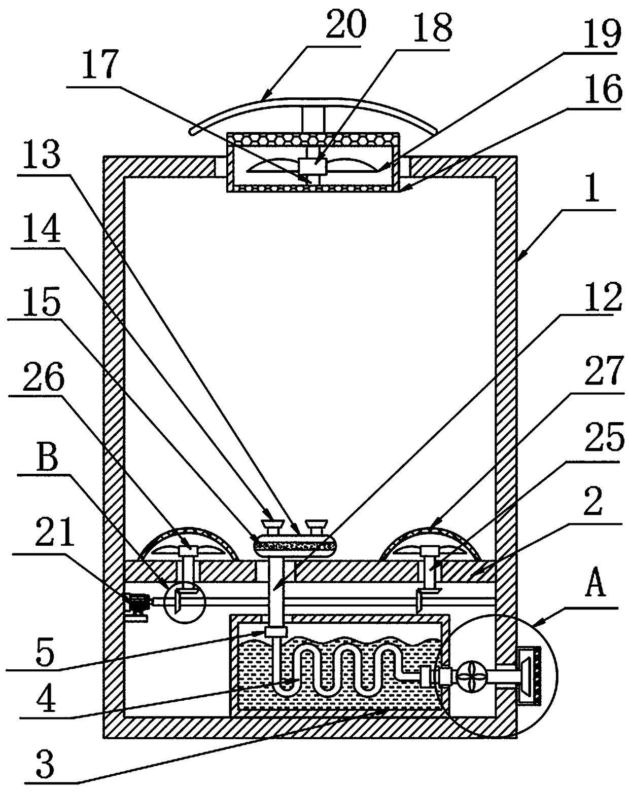
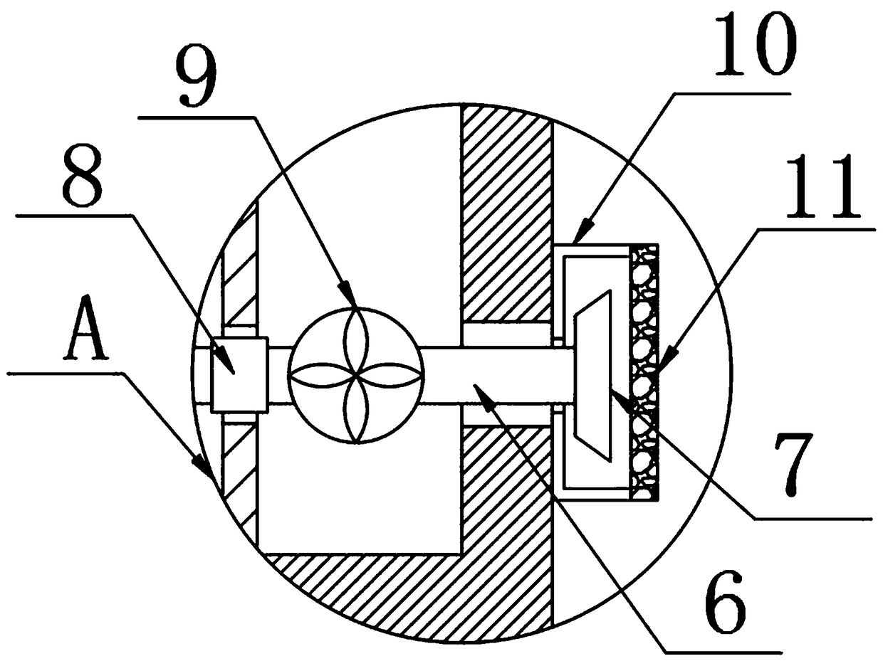
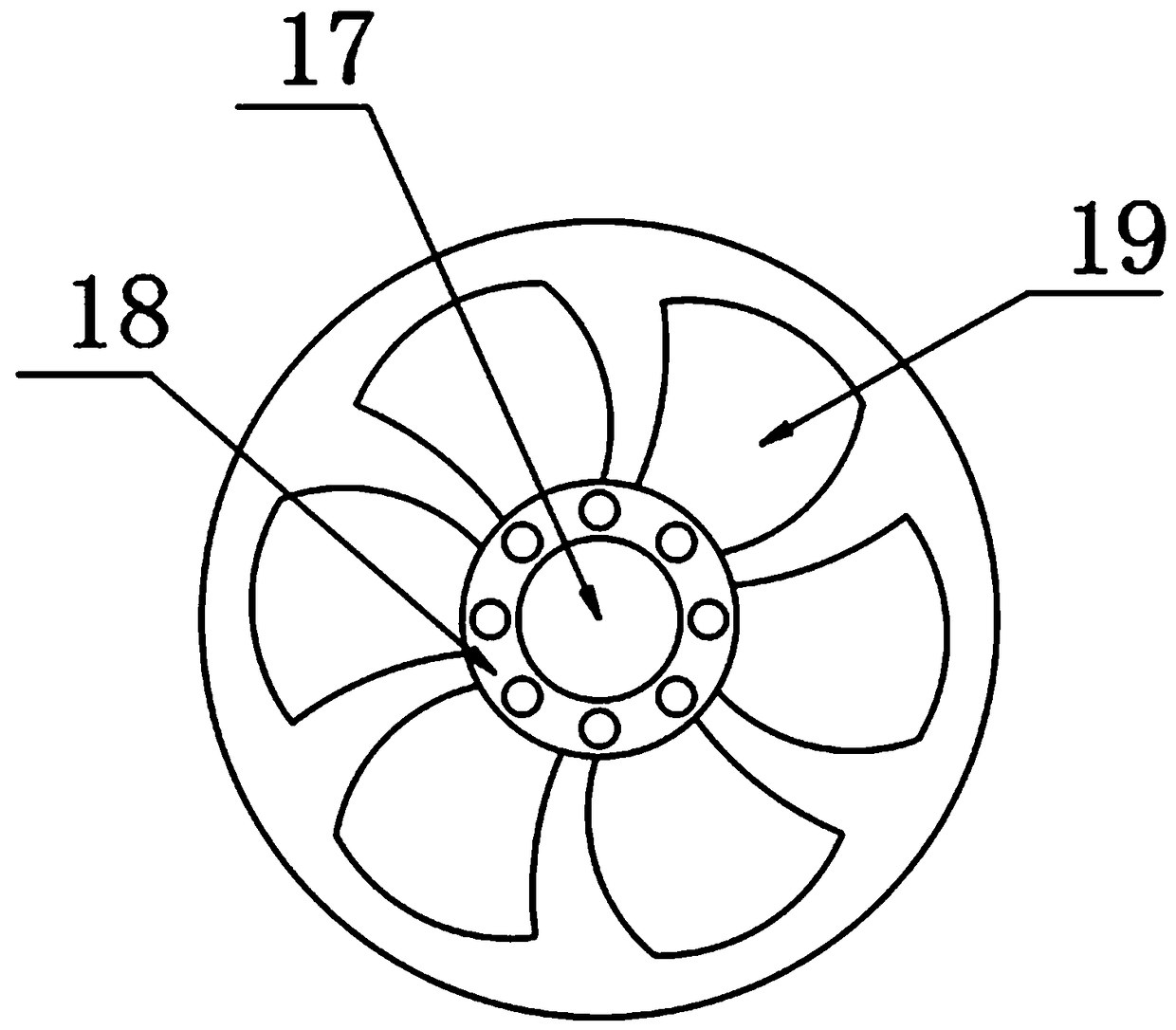
[0021] The present invention provides such Figure 1-5 The power distribution cabinet shown is convenient for ventilation and heat dissipation, including a power distribution cabinet body 1, the power distribution cabinet body 1 is fixedly connected with a heat insulation board 2 near the inner wall of the bottom, through the heat insulation board 2, the power distribution cabinet body 1 is prevented from The internal air affects the function of the cooling bo...


PUM


Abstract

The invention discloses a power distribution cabinet providing convenience for ventilation and heat dissipation. The power distribution cabinet comprises a power distribution cabinet body, the portion, close to the inner wall of the bottom, of the power distribution cabinet body is fixedly connected with a thermal baffle, and a cooling box is arranged on the bottom wall inside the power distribution cabinet body; a coil pipe is arranged inside the cooling box, two ends of the coil pipe are both in through connection with pipeline interfaces, and one end of the coil pipe is in through connection with an air suction pipe through one interface; one end of the air suction pipe penetrates through the cooling box and the inside of the power distribution cabinet, extends to the outside, and is inthrough connection with a sucker, and the through portion between the air suction pipe and the cooling box is fixedly sleeved with mechanical seal; an exhaust fan is connected with two ends of the air suction pipe, an air suction box is arranged on the surface of the sucker, and filter cotton is arranged on the surface of the air suction box. By arranging the coil pipe, drying cotton and a firstshutter, the power distribution cabinet can effectively cool the inside of the power distribution cabinet body, avoid that an excess temperature inside the power distribution cabinet body destroys electric devices, and improve the heat dissipation and cooling efficiency of the power distribution cabinet body.

Description

technical field [0001] The invention relates to the technical field of power distribution cabinet equipment, in particular to a power distribution cabinet that is convenient for ventilation and heat dissipation. Background technique [0002] At present, there are many power distribution meters in the power distribution cabinet. These power distribution meters will generate a lot of heat during operation, causing the internal temperature of the power distribution cabinet to rise continuously. The traditional power distribution cabinet will be equipped with heat sinks However, the heat dissipation effect of the heat sink is poor. When the power distribution cabinet is used for a long time, the temperature inside the power distribution cabinet will continue to rise. The high temperature will affect the normal operation of the equipment, and even cause a fire due to the overheating of the equipment in severe cases. , and the heat dissipation function of the existing power distri...

Claims


Application Information

Patent Timeline
Patent Type & Authority Applications(China)
IPC IPC(8): H02B1/30H02B1/56H02B1/28
CPCH02B1/30H02B1/28H02B1/565
Inventor 于娟
Owner DONGGUAN ZHIPEI ELECTROMECHANICAL TECH CO LTD
Why Eureka
Try Eureka