
Enable control circuit, switching power supply controller and control method

A control circuit and switching power supply technology, applied in the field of power electronics, can solve the problems of high cost and large standby power consumption, and achieve the effects of low cost, low power consumption and wide application range

Pending Publication Date: 2018-08-21
SHENZHEN LINGQI SEMICON CO LTD
View PDF0 Cites 0 Cited by
  • Summary
  • Abstract
  • Description
  • Claims
  • Application Information

AI Technical Summary

Problems solved by technology

After receiving the external trigger (switch SW1), the switch closed loop is realized through the relay (KW1), which makes the switch operation more humanized, but the processing of external signals requires system power supply (such as image 3 The LV+, LV- low-voltage power supply additionally uses a backup power supply), resulting in excessive standby power consumption and high cost
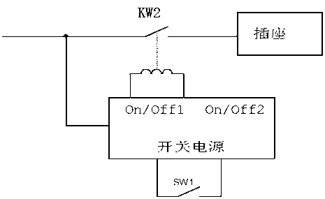
[0005] Method 3: On the basis of method 2, use the power supply for the relay (KW1) in the standby mode of the subsequent switching power supply (such as image 3 As shown), it solves the power supply problem of LV+ and LV-, that is, using On / Off1 to control the opening and closing of the relay, which reduces the cost to a certain extent, but requires additional devices to realize On / Off2 to break the output of the switching power supply to prevent failure. The expected situation occurs, and there are still a series of problems such as excessive standby power consumption and high cost

Method used


Image

  • Enable control circuit, switching power supply controller and control method
  • Enable control circuit, switching power supply controller and control method
  • Enable control circuit, switching power supply controller and control method

Examples


Embodiment Construction

[0047] The design idea of ​​the present invention is: the present invention uses the button to control the relay, arranges the button outside the switching power supply controller, and integrates related circuits inside the switching power supply controller.

[0048] The invention provides an enabling control circuit, a switching power supply controller and an enabling control method. To be introduced below.

[0049] 1: Enable control circuit

[0050] The enabling control circuit of the present invention is suitable for existing switching power supply controllers.

[0051] Such as Figure 4 Shown is the application block diagram of the enable controller. Figure 5 Circuit diagram for the entire circuit. The enabling control circuit of the present invention includes a key switch (sw1 in the figure) and a control circuit. The control circuit includes a series circuit connected in sequence, a trigger circuit and an enabling control circuit; the output end of the enabling con...


PUM


Abstract

The invention provides an enable control circuit, a switching power supply controller and a control method. The enable control circuit comprises a key switch, wherein one end of the key switch is grounded, and the other end of the key switch is connected with a KEY interface of the switching power supply controller; the KEY interface is sequentially connected with a first blanking circuit, a firsthysteresis control circuit, a trigger control circuit and the enable control circuit. The enable control circuit is simple in structure and low in cost, and has a relatively good application prospect.

Description

technical field [0001] The invention relates to the technical field of power electronics, in particular to an enabling control circuit, a switching power supply controller, and a control method. Background technique [0002] Enable control, that is, a control method that requires external triggering to start. In the prior art, for switching power supplies that require enabling control, such as AC / DC power supplies, power strips with switch control functions, etc., the following methods are mainly used for control: [0003] Method 1: Use the direct switch lock button to control (such as figure 1 ), the button generally has the corresponding current on-off capability, and it can directly close the loop and turn off, but the contact is easy to age and may be accompanied by electric sparks, arcing and other discharge phenomena. operate. [0004] Method 2: Carry out intelligent switch control (such as figure 2 shown). After receiving the external trigger (switch SW1), t...

Claims


Application Information

Patent Timeline
Patent Type & Authority Applications(China)
IPC IPC(8): H02M1/36
CPCH02M1/36Y02B70/10
Inventor 李友玲高建龙
Owner SHENZHEN LINGQI SEMICON CO LTD
Learn More