Rotation device and rotation radar device

A rotating device and radar technology, applied in electromechanical devices, rotating current collectors, bearing assembly, etc., can solve problems affecting the quality of sensor signal transmission and power supply stability, and achieve the effect of improving stability and ensuring work stability.

Active Publication Date: 2018-08-21
SHEN ZHEN 3IROBOTICS CO LTD
View PDF8 Cites 4 Cited by
  • Summary
  • Abstract
  • Description
  • Claims
  • Application Information

AI Technical Summary

Problems solved by technology

[0003] However, many sensing devices are equipped with a rotatable platform. When the sensor of the smart device is placed on the rotatable platfor

Method used


Image

  • Rotation device and rotation radar device
  • Rotation device and rotation radar device
  • Rotation device and rotation radar device

Examples


no. 1 example

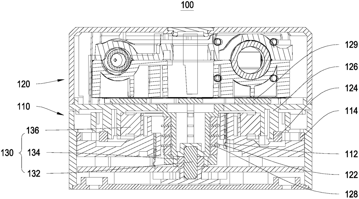
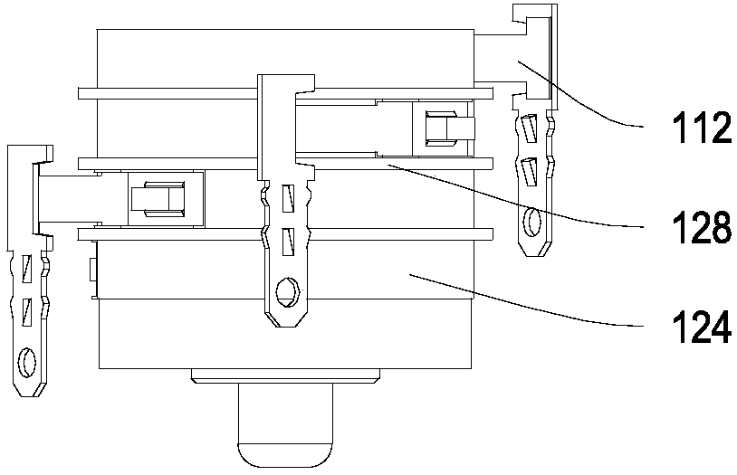
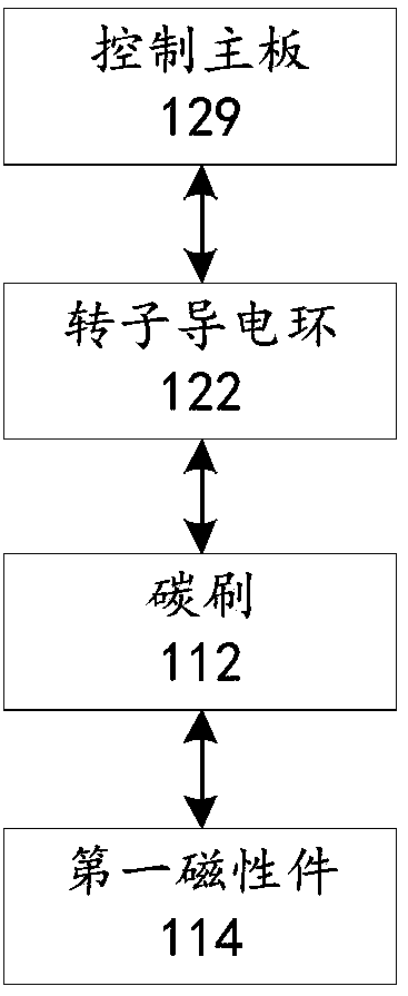
[0040]According to the applicant's research, it is found that the existing rotating platforms such as unmanned aerial vehicle platforms and automobile activity radar platforms often use slip rings to transmit energy and information when collecting and transmitting data and supplying power. When slip rings are used for power supply and communication information transmission, the stability of the rotating platform is extremely high. The rotating platform may start and stop frequently during the rotation. If the stability of the rotating platform is not good, there will be problems of poor information collection quality, unstable power supply and communication. In order to solve the above problems, the first embodiment of the present invention provides a rotating device 100, please refer to figure 1 , figure 1 It is a structural sectional view of a rotating device provided in the first embodiment of the present invention.

[0041] The rotating device 100 includes a fixed platfo...

no. 2 example

[0058] Please refer to Figure 4 , Figure 4 It is a schematic structural diagram of a rotating radar device provided by the second embodiment of the present invention.

[0059] The difference between the rotating radar device 200 and the rotating device 100 is that the rotating radar device 200 also includes a radar module 210 connected to the control board 129, and at the same time, the rotating platform 120 is also provided with a radar for fixing the radar module 210. Fixed area.

[0060] The radar module 210 is installed in the radar fixed area. The radar module 210 collects multi-angle environmental information during the rotation of the rotating platform 120 and transmits it to the control board 129 to complete the transmission of the environmental information. At the same time, the control information related to the radar module 210 and the rotating platform 120 is also generated by controlling the main board 129, including the rotation control information for contro...


PUM


Abstract

The invention provides a rotation device and a rotation radar device and belongs to the technical field of an electronic communication rotation platform. The rotation device comprises a fixed platformand a rotation platform. The top end of the fixed platform and the bottom end of the rotation platform are rotationally connected through a rotation shaft, a first bearing and second bearings. The rotation shaft is in penetration connection with inner ring of the first bearing. The fixed platform comprises carbon brushes set around the rotation shaft and first magnetic elements set around the second bearings. The rotation platform comprises second magnetic elements matching the first magnetic elements and rotor conductive rings in matching connection with the carbon brushes. An outer ring ofthe first bearing is connected with the fixed platform. The inner rings of the second bearings are connected with the fixed platform. The outer rings of the second bearings are connected with the rotation platform. The stable power supply and communication of the rotation platform and the fixed platform are realized, and the rotation stability of the rotation device is greatly improved.

Description

technical field [0001] The invention relates to the technical field of electronic communication rotating platforms, in particular, to a rotating device and a rotating radar device. Background technique [0002] With the rapid development of economic level and science and technology, the Internet of Things and intelligent robots have followed the pace of the Internet era and began to enter people's daily life on a large scale. Almost all smart devices, such as unmanned aerial vehicles, unmanned vehicles and intelligent robots, need to monitor the surrounding environment through sensors to obtain relevant environmental parameters, so that the control device can calculate and process the environmental parameters to obtain the device An operating parameter controls the operation of the smart device. [0003] However, many sensing devices are equipped with a rotatable platform. When the sensor of the smart device is placed on the rotatable platform, if the rotation of the rotata...

Claims


Application Information

Patent Timeline
IPC IPC(8): H04B5/00G08C17/04H02K7/18F16M11/06
CPCH02K7/1807H04B5/0031H04B5/0037H04B5/0081G08C17/04F16M11/06H02K13/003F16M11/08F16M11/18H01R39/64F16C41/002F16C2380/00G01S7/02H01Q3/04H01R2201/20
Inventor 杨勇宫海涛曾思远高亭
Owner SHEN ZHEN 3IROBOTICS CO LTD
Why Eureka
Try Eureka