
Continuously variable planetary gear mechanism

A technology for planetary transmissions and transmissions, applied in vehicle transmissions, friction transmissions, belts/chains/gears, etc., which can solve problems such as increased transmission costs, increased wear, and adverse effects on planetary transmission efficiency and transmission ratio

Active Publication Date: 2018-08-21
ROLLESS GMBH
View PDF18 Cites 0 Cited by
  • Summary
  • Abstract
  • Description
  • Claims
  • Application Information

AI Technical Summary

Problems solved by technology

On the other hand, increased axial forces lead to higher frictional losses in the axial bearing between the torque transmission element and the housing
Usually, the contact angle preset by the ball geometry therefore has a negative effect on the efficiency and the achievable transmission ratio of the planetary transmission
A further disadvantage of the planetary transmission according to DE 10 2008 058074 A1 is that, depending on the gear ratio adjustment, different speeds occur in the four contacts, which in turn cause slippage losses due to the lack of force symmetry
In addition to the required installation space, the considerable size of the transmission element mainly also has a negative effect on the weight of the transmission
Since only point contact can be produced between the conical surface of the transmission element and the outwardly arched surface of the rolling elements, extremely high Hertzian pressures occur at the contact points, which lead to increased wear
As can also be seen, the outwardly curved sections of the rolling elements have a curved contour, which is difficult to manufacture and thus also increases the costs of the transmission
In addition, it should be pointed out that this type of transmission can only be shifted with difficulty under load, because in most transmission positions, the three-point bearing of the outer contact part is not formed with respect to the supporting contact part of the planetary rolling element. symmetry

Method used


Image

  • Continuously variable planetary gear mechanism
  • Continuously variable planetary gear mechanism
  • Continuously variable planetary gear mechanism

Examples


Embodiment Construction

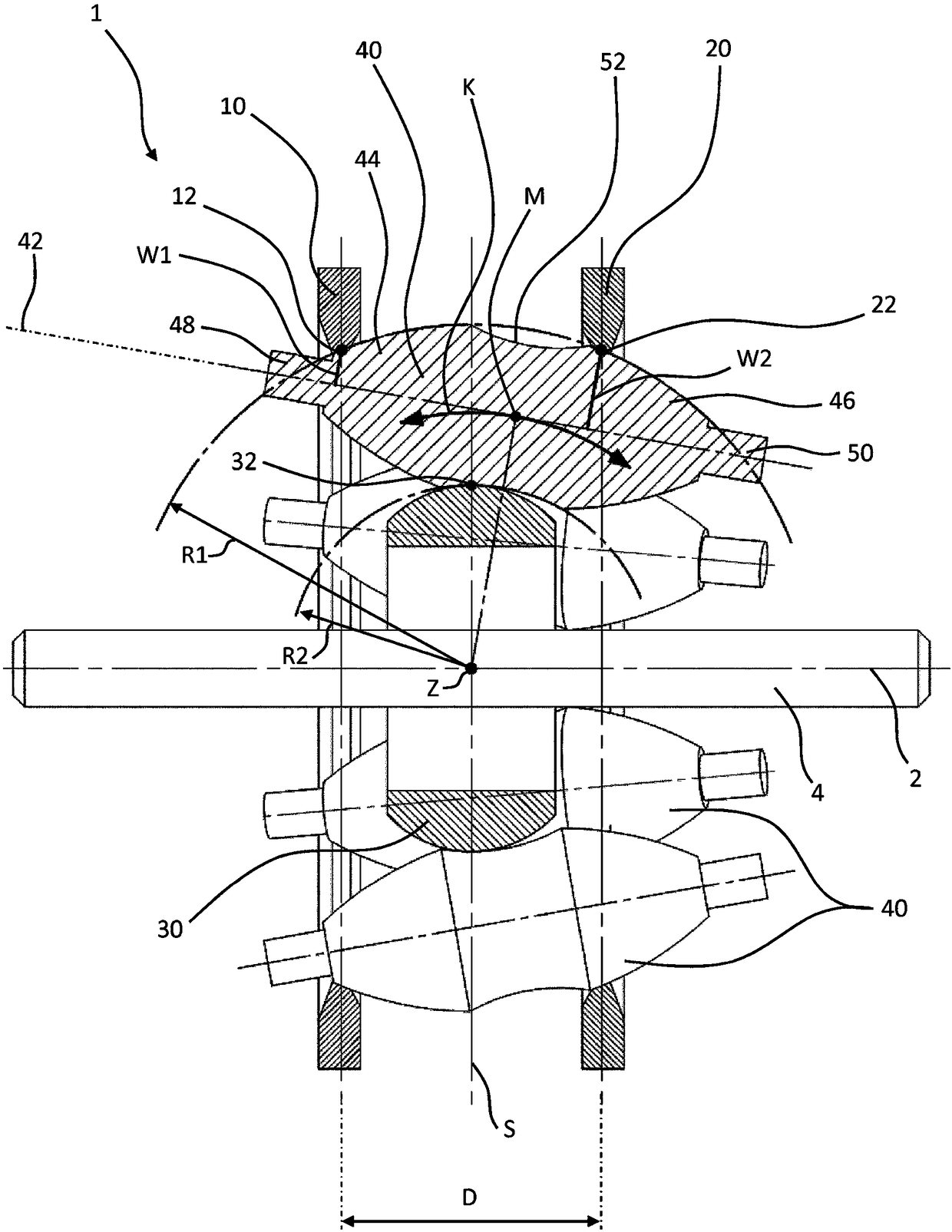
[0051] Figure 1a A schematic sectional view of the components essential for the transmission function of the first embodiment of the continuously variable planetary transmission is shown. They form the basis for a transmission which can be used in a wide variety of fields and which is correspondingly adapted to the prevailing operating conditions. The transmission according to the invention is referred to as two embodiments of a complete bicycle hub transmission Figure 9 with 10 to illustrate.

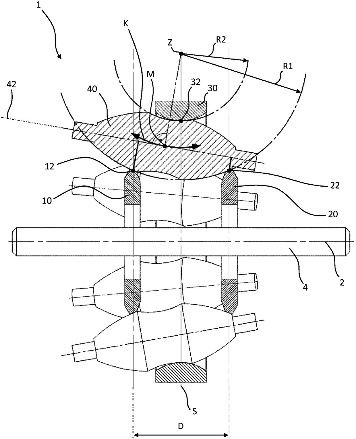
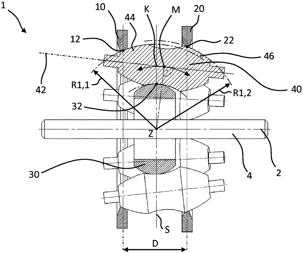
[0052] A sectional view is shown in each case in FIGS. 1 to 6 , 9 and 10 . In this case, the section is defined by a straight line between the transmission axis 2 and the longitudinal axis 42 of the planetary roller bodies 40 .

[0053] Figure 1a A transmission axis 2 is shown, which can be designed, for example—but not necessarily—as a continuous transmission shaft 4 , around which a first transmission element 10 , a second transmission element 20 , at least one planetary rollin...


PUM


Abstract

A continuously variable planetary gear mechanism (1) comprises a first and a second transmission element (10, 20) which are mounted at a fixed axial spacing (D) from one another for rotation about a gear mechanism axis (2), and at least one supporting element (30) which is substantially radially fixed with respect to the gear mechanism axis (2), and at least one elongate planetary roller body (40)which is rotationally symmetrical about its longitudinal axis (42) and is designed to rotate thereabout. The first transmission element (10) has at least one first contact point (12), the second transmission element (20) has at least one second contact point (22), and the at least one supporting element (30) has at least one third contact point (32), and at each contact of the points (12, 22, 32)there is a frictional rolling connection to a planetary roller body (40), such that the at least one planetary roller body (40) is held about the gear mechanism axis (2) for movement between the first and the second transmission elements (10, 20) and the at least one supporting element (30). A displacement of the centre point (M) of the at least one planetary roller body (40) relative to the transmission elements (10, 20) brings about a change in the transmission ratios of the planetary gear mechanism (1). The at least one supporting element (30) is substantially axially fixed relative to thefirst and second transmission elements (10, 20).

Description

technical field [0001] The invention relates to continuously variable planetary transmissions for machines and vehicles, in particular for vehicles propelled by muscular power, such as bicycles, motorized bicycles and electric bicycles. Background technique [0002] In bicycles, known hub transmissions are increasingly being used, which are generally designed as planetary transmissions. In principle, hub transmissions can be differentiated between continuously variable transmissions (eg NuVinci CVP N360) and transmissions with straight or inclined toothing and fixed gear stages (eg Rohloff Speedhub, Shimano Alfine). The increased supply of motorized bicycles and electric bicycles also places new demands on bicycle transmissions. A noticeable shifting noise is audible in conventional, form-fitting chain-shift transmissions and rear hub transmissions, and when these transmissions are shifted under load without disengaging the transmission elements, this can lead to increased ...

Claims


Application Information

Patent Timeline
Patent Type & Authority Applications(China)
IPC IPC(8): F16H15/50B62M11/16B62M11/12
CPCB62M11/12F16H15/50B62M11/16
Inventor 沃尔夫冈·罗迪
Owner ROLLESS GMBH
Learn More