
Coextruded jacket for flame retardant fiber optic cables

A fiber optic cable and cable sheath technology, applied in the direction of insulated cables, cables, optics, etc., can solve problems such as sheath cracking, achieve excellent bonding strength, eliminate outer layer wrinkling and/or separation effects

Inactive Publication Date: 2018-08-21
CORNING OPTICAL COMM LLC
View PDF7 Cites 1 Cited by
  • Summary
  • Abstract
  • Description
  • Claims
  • Application Information

AI Technical Summary

Problems solved by technology

This low ultimate elongation of LSZH material can lead to jacket cracking when cable products are subjected to typical handling and installation loads

Method used


Image

  • Coextruded jacket for flame retardant fiber optic cables
  • Coextruded jacket for flame retardant fiber optic cables
  • Coextruded jacket for flame retardant fiber optic cables

Examples


Embodiment Construction

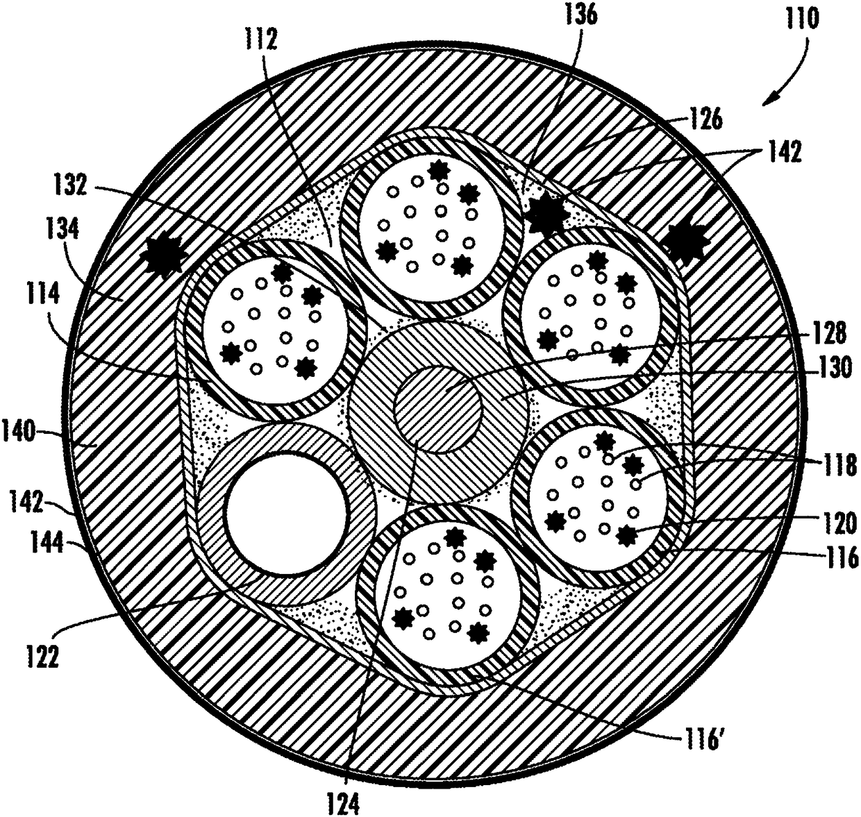
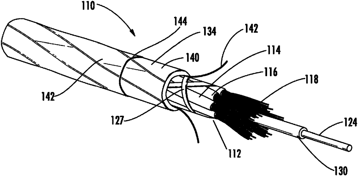
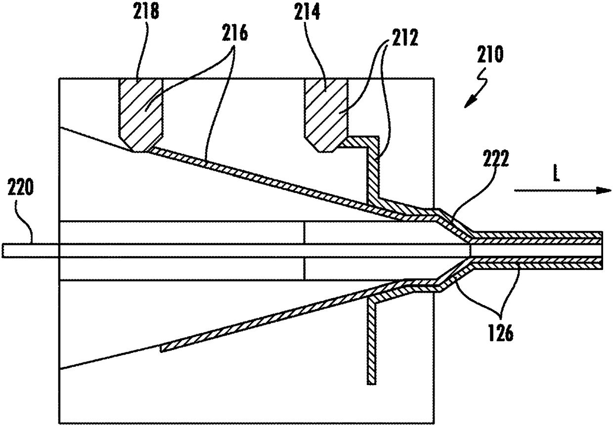
[0017] Before turning to the following detailed description and accompanying drawings, which illustrate exemplary embodiments, it is to be understood that the inventive technology is not limited to the details or methodology set forth in the detailed description or shown in the drawings. For example, features and attributes associated with an embodiment shown in one of the drawings or described in text related to one of the embodiments would apply to the ones in the drawings, as will be understood by those of ordinary skill in the art Other embodiments are shown in another and / or described elsewhere in the text.

[0018] refer to figure 1 , the cable in the form of a fiber optic cable 110 may be an external device loose tube cable, an indoor cable with fire / flame retardant properties, an indoor / outdoor cable, or another type of cable (such as a hybrid with micromodules or including conductive elements) fiber optic cables for data center interconnect cables). According to an ...


PUM

PropertyMeasurementUnit
The average thicknessaaaaaaaaaa
Thicknessaaaaaaaaaa

Abstract

A fiber optic cable comprises a core subassembly comprising at least one optical fiber and a tube surrounding the optical fiber. A multi-layered jacket surrounds the core subassembly, wherein the jacket comprises an inner layer comprising a flame retardant (FR) material and an outer layer comprising a non flame retardant material having a lower coefficient of friction than the flame retardant material. A method of manufacturing an optical fiber cable includes providing a core subassembly and co-extruding a multi-layered jacket around the core subassembly, wherein the multi-layered jacket includes an inner layer comprising a flame retardant (FR) material and an outer layer comprising a non flame retardant material having a lower coefficient of friction than the flame retardant.

Description

[0001] Cross References to Related Applications [0002] This application claims the benefit of priority to U.S. Provisional Application No. 62 / 260,843, filed November 30, 2015, under 35 U.S.C. §119 and is incorporated herein by reference. technical field [0003] Aspects of the present disclosure relate generally to cables, such as fiber optic cables, that can support and carry optical fibers and other cable components. Background technique [0004] Fiber optic cables, especially those in jurisdictions and applications with strict fire and smoke regulations, are designed to minimize the spread of fire, smoke, toxic gases, and other fire-related hazards. Often thick jackets of flame retardant (FR) and low smoke zero halogen (LSZH) materials are used to meet the demands of these types of fiber optic cables. However, these types of cables are often intended for installation in ducts, whereby the cable is blown or sprayed into the duct, depending on the installation method. T...

Claims


Application Information

Patent Timeline
IPC IPC(8): G02B6/44
CPCG02B6/4434G02B6/4436G02B6/4438H01B7/295G02B6/475G02B6/52B29D11/00663G02B6/441G02B6/4433G02B6/4486
Inventor 安妮·杰曼·布鲁涅尔安娜·利斯塔克艾伦·迈克尔·米勒塞巴斯蒂安·奥尔斯泽夫斯基卡塔知娜·西诺韦克
Owner CORNING OPTICAL COMM LLC
Learn More