Supercharge Your Innovation With Domain-Expert AI Agents!

Pushing and sliding composite slanted motion mechanism and pushing and sliding composite slanted motion mold

A motion mechanism and mold technology, applied in the field of push-slip compound oblique motion mechanism and push-slip compound oblique motion mold, can solve the problems of difficult operation, complex mold structure, etc., and achieve simple structure, convenient manufacturing, mechanism and mold work. reliable results

Inactive Publication Date: 2018-08-24
SUZHOU INST OF TRADE & COMMERCE
View PDF9 Cites 1 Cited by
  • Summary
  • Abstract
  • Description
  • Claims
  • Application Information

AI Technical Summary

Problems solved by technology

[0004] The purpose of the present invention is to provide a push-slip compound oblique motion mechanism and a push-slide compound oblique motion mold to solve the problem that the existing mold has a complex mold structure and is not easy to operate when performing oblique short-distance core pulling

Method used


Image

  • Pushing and sliding composite slanted motion mechanism and pushing and sliding composite slanted motion mold
  • Pushing and sliding composite slanted motion mechanism and pushing and sliding composite slanted motion mold
  • Pushing and sliding composite slanted motion mechanism and pushing and sliding composite slanted motion mold

Examples


Embodiment Construction

[0029] The technical solutions in the embodiments of the present invention will be clearly and completely described and discussed below in conjunction with the accompanying drawings of the present invention. Obviously, what is described here is only a part of the examples of the present invention, not all examples. Based on the present invention All other embodiments obtained by persons of ordinary skill in the art without creative efforts fall within the protection scope of the present invention.

[0030] In order to facilitate the understanding of the embodiments of the present invention, specific embodiments will be taken as examples for further explanation below in conjunction with the accompanying drawings, and each embodiment does not constitute a limitation to the embodiments of the present invention.

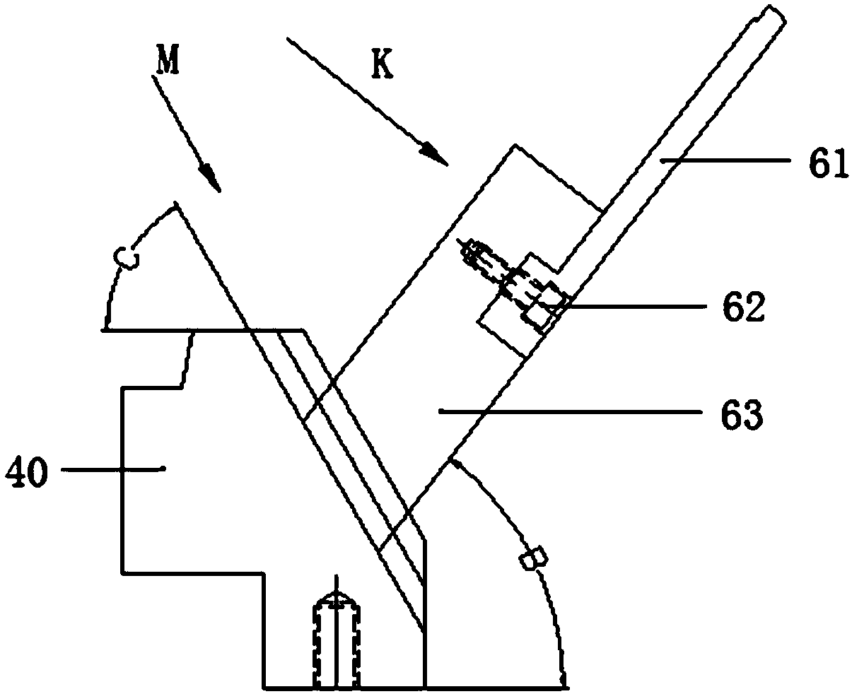
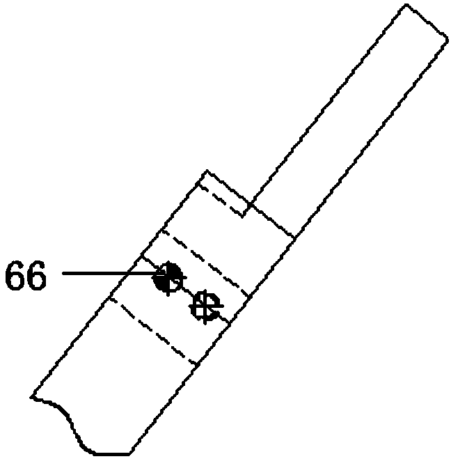
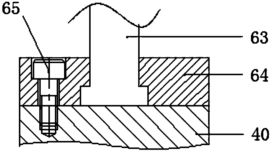
[0031] A pushing-sliding compound oblique movement mechanism provided in this embodiment includes a core-pulling assembly arranged on the movable mold part of the core-pu...


PUM


Abstract

The invention provides a pushing and sliding composite slanted motion mechanism. The pushing and sliding composite slanted motion mechanism comprises a core pulling assembly and a slanted ejection assembly. The core pulling assembly comprises a sliding block, a sliding block insert, a pressure bar and a sliding block seat. The sliding block is mounted on the bevel of the sliding block seat throughthe pressure bar and can slide. The lower end of the sliding block insert is fixedly connected with the sliding block, and the upper end of the sliding block insert is used for forming a slanted outer hole of a product and completing core pulling under driving of a movable mold part. The slanted ejection assembly comprises a slanted ejector block, a slanted ejection locking piece and a slanted ejection base. The slanted ejector block is locked onto the slanted ejection base through the slanted ejection locking piece, and the slanted ejection locking piece can slide freely. The slanted ejectorblock is used for pushing out a formed product in a slanting mode for demolding. The upper end of the sliding block insert is located in a mold core insert before core pulling and is drawn out from the mold core insert after core pulling. The invention further provides a pushing and sliding composite slanted motion mold comprising the pushing and sliding composite slanted motion mechanism. Through the pushing and sliding composite slanted motion mechanism and the pushing and sliding composite slanted motion mold, the problem that an existing mold is complex in structure and not easy to operate during slanting short-distance core pulling. The pushing and sliding composite slanted motion mechanism and the pushing and sliding composite slanted motion mold are simple in structure, convenientto manufacture and reliable in operation.

Description

technical field [0001] The invention relates to the technical field of mold design, in particular to a push-slide composite oblique motion mechanism and a push-slide composite oblique motion mold. Background technique [0002] Slanted holes often appear in the design and manufacture of parts. Since the oblique hole is at a certain angle to the mold opening direction, the parts generally cannot be demolded directly, so it is necessary to consider the problem of oblique core pulling when designing the mold structure. [0003] At present, the oblique core-pulling methods for plastic molds mainly include: one is to drive the slider to pull the core through the oblique guide column; It is to make the inclined core of the fixed mold into an insert, and take it out manually after the mold is opened. Although the first two methods can achieve core pulling in structure, they are always a single core pulling. When some plastic products with special structures need to pull cores in 2...

Claims


Application Information

Patent Timeline
Patent Type & Authority Applications(China)
IPC IPC(8): B29C39/26B29C39/36
Inventor 王成
Owner SUZHOU INST OF TRADE & COMMERCE
Features
  • R&D
  • Intellectual Property
  • Life Sciences
  • Materials
  • Tech Scout
  • Unparalleled Data Quality
  • Higher Quality Content
  • 60% Fewer Hallucinations
Learn More