
Stable gel pen

A gel pen, stable technology, applied in the field of stationery, can solve problems such as easy loss of the pen cap, not allowed to stably fix the refill, unstable writing, etc., to achieve the effect of avoiding the loss of the pen cap, omitting the spring structure, and high writing stability

Inactive Publication Date: 2018-08-24
XINCHANG COUNTY YINGDAO TECH CO LTD
View PDF1 Cites 0 Cited by
  • Summary
  • Abstract
  • Description
  • Claims
  • Application Information

AI Technical Summary

Problems solved by technology

[0002] The pen cap on the traditional signature pen is generally an independent structure with the pen holder. When using the pen cap, open the pen cap and put the pen cap on the top of the pen holder, but the pen cap of the signature pen with this structure is easy to lose;
[0003] The existing patent number is ZL201510060888.2, and the name is "a kind of pen". It is a Chinese invention patent, which adopts the upper pen holder and the lower pen holder which are matched with sockets. By moving the lower pen holder, the tip of the pen core is exposed or hidden. The structure is simple, and the traditional detachable pen cap is omitted, as well as the spring structure, but when the pen tip is exposed for writing, the lower pen barrel must be held in whole or in part, because the pen core is fixed with the upper pen barrel, and the upper pen barrel and the lower pen barrel are sleeved Active fit, so the lower pen holder and the pen core are not fastened structures, resulting in instability when writing. Although a snap ring is provided in the lower pen holder to stabilize the pen core, in order to avoid affecting the movable fit between the upper pen holder and the lower pen holder sleeve, the snap ring The ring does not allow a stable fixation of the cartridge in the axial direction, so it is necessary to improve it

Method used


Image

  • Stable gel pen
  • Stable gel pen
  • Stable gel pen

Examples


Embodiment Construction

[0034] The following are specific embodiments of the present invention and in conjunction with the accompanying drawings, the technical solutions of the present invention are further described, but the present invention is not limited to these embodiments.

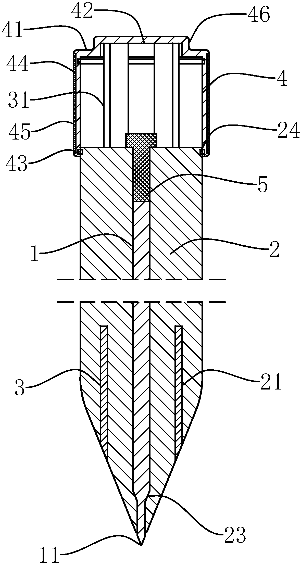
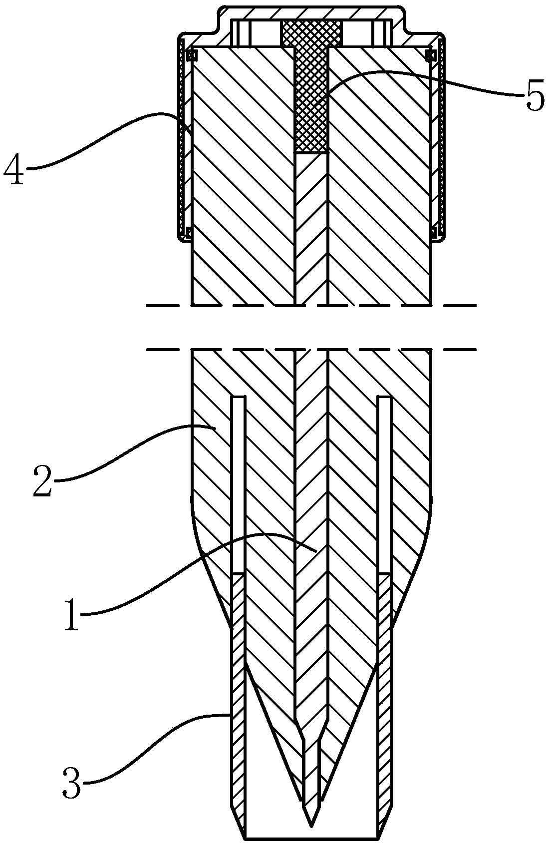
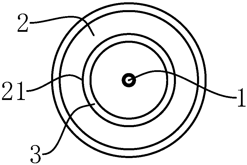
[0035] like Figure 1-5 As shown, a stable gel pen of the present invention comprises a round rod-shaped penholder 2, a pen core 1 is fixed in the penholder 2, the bottom end of the pen core 1 has a nib 11 protruding from the bottom end of the penholder 2, and a penholder 2 is provided on the wall of the penholder. There is a sleeve-shaped sleeve groove 21, and the slot of the sleeve groove 21 is located at the bottom end of the pen holder 2. The sleeve groove 21 has a sleeve-shaped outer groove wall and an inner groove wall coaxially arranged with the pen holder 2, and also includes several transverse grooves located in the pen holder 2. The cross-section is an arc-shaped adjustment hole 22, the top and bottom ends of the...


PUM


Abstract

The invention provides a stable gel pen, and belongs to the stationery field. The stable gel pen solves the problem that a pen cap of an existing gel pen is prone to getting lost or writing is unstable. The stable gel pen comprises a pen holder fixed to a refill, and a sleeve groove is formed in the holder wall of the pen holder. A plurality of adjusting holes with the arc cross sections are further included, wherein the adjusting holes are located in the pen holder. A pen sleeve is further included. A plurality of adjusting rods with the arc cross sections are fixed to the top end of the pensleeve. The pen sleeve is located in the sleeve groove in a matched manner. The multiple adjusting rods sequentially penetrate the multiple adjusting holes in a matched manner. The top end of the pensleeve abuts against the groove bottom of the sleeve groove, and the bottom end of the pen sleeve is aligned with the outer wall of the part, at the corresponding position, of the pen holder. The pencap movably sleeving the outer wall of the top end of the pen holder is further included. A cap plate is fixed to the top end of the pen cap. The top ends of the multiple adjusting rods are fixed to the cap plate, the cap plate can be pushed towards the bottom end of the pen holder, the pen cap drives the adjusting rods to move, the pen sleeve is moved out of the sleeve groove and wraps the outerside of a pen point, and the cap plate abuts against the top end of the pen holder at the time. According to the gel pen, writing stability can be guaranteed, and adjustment is convenient.

Description

technical field [0001] The invention belongs to the technical field of stationery and relates to a stable gel pen. Background technique [0002] The pen cap on the traditional signature pen is generally an independent structure with the pen holder. When using the pen cap, open the pen cap and put the pen cap on the top of the pen holder, but the pen cap of the signature pen with this structure is easy to lose; [0003] The existing patent number is ZL201510060888.2, and the name is "a kind of pen". It is a Chinese invention patent, which adopts the upper pen holder and the lower pen holder which are matched with sockets. By moving the lower pen holder, the tip of the pen core is exposed or hidden. The structure is simple, and the traditional detachable pen cap is omitted, as well as the spring structure, but when the pen tip is exposed for writing, the lower pen barrel must be held in whole or in part, because the pen core is fixed with the upper pen barrel, and the upper pe...

Claims


Application Information

Patent Timeline
IPC IPC(8): B43K23/08B43K3/00
CPCB43K23/08B43K3/00
Inventor 张云生
Owner XINCHANG COUNTY YINGDAO TECH CO LTD
Learn More