Stepped volute structure, centrifugal fan and air blowing device

A volute and ladder technology is applied in the field of stepped volutes and centrifugal fans and blowing devices including the same, which can solve the problems of airflow backflow, affecting work efficiency, etc., and achieve the effect of improving noise and reducing eddy current noise.

Pending Publication Date: 2018-08-24
GREE ELECTRIC APPLIANCES INC
View PDF10 Cites 13 Cited by
  • Summary
  • Abstract
  • Description
  • Claims
  • Application Information

AI Technical Summary

Problems solved by technology

[0004] Therefore, the technical problem to be solved by the present invention is to overcome the defects in the prior art that the position of the front disc of the fan blade in the volute is prone to backflow of air flow, affects work efficiency or generates eddy current noise

Method used


Image

  • Stepped volute structure, centrifugal fan and air blowing device
  • Stepped volute structure, centrifugal fan and air blowing device
  • Stepped volute structure, centrifugal fan and air blowing device

Examples


Embodiment 1

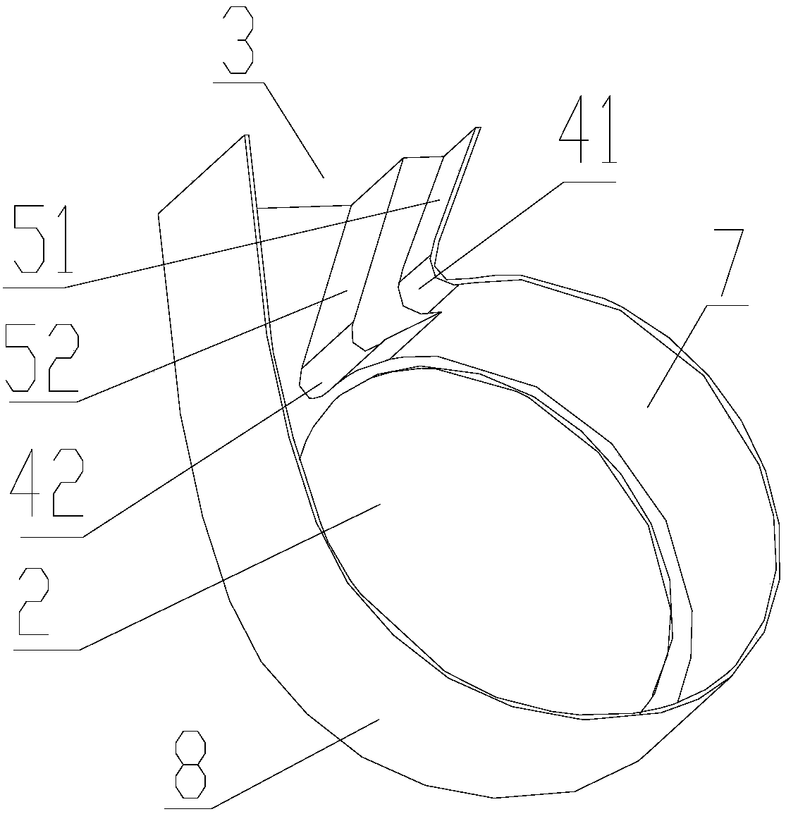
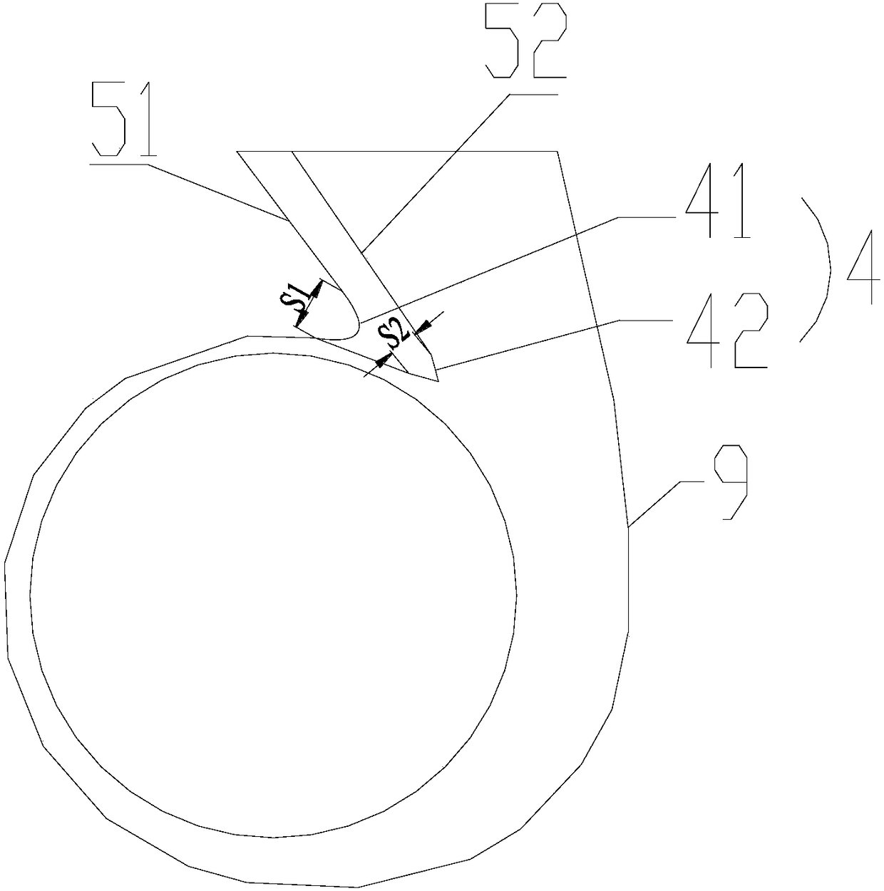
[0035] This embodiment provides a stepped volute structure, such as figure 2 As shown, it includes: a housing 1, which is provided with an air inlet 2 and an air outlet 3; a plurality of volute tongues 4 arranged side by side along the thickness direction of the volute; a volute with the same number as the volute tongue 4 The volute tongue side wall surface 5 is arranged at the position of the volute case diffuser section 6, and each of the volute case volute tongue side wall surfaces 5 is respectively connected with each corresponding volute tongue 4; several of the volute tongues 4 1. The volute tongue side wall surface 5 is arranged in a step shape, extending along the air inlet 2 to the thickness direction of the housing 1, and the volute tongue side wall surface 5 is 100mm away from the fan blade front disk 7 The distance gradually increases.

[0036] The stepped volute structure adopted in this embodiment, such as figure 2 As shown, the number of steps is 2. Specifi...

Embodiment 2

[0043] This embodiment provides a centrifugal fan, such as Figure 7 As shown, it includes the stepped volute structure described in Embodiment 1; and, the fan blade 10 is arranged at the position corresponding to the air inlet 2 inside the stepped volute structure, and the stepped volute structure is correspondingly provided with a wind blade 10 The blade front disc 7 and the fan blade rear disc 8, after the fan blades rotate, the air is driven to flow into the stepped volute structure from the air inlet 2, and then the wind is driven to flow out from the air outlet 3.

[0044] The centrifugal fan provided in this embodiment adopts a stepped volute structure, and compared with the traditional centrifugal volute structure, the air volume can be increased by 80-150m 3 / h, the noise is reduced by 0.8-1.7dB.

Embodiment 3

[0046] This embodiment provides a blower device, including at least one set of centrifugal fans provided in Embodiment 2.


PUM


Abstract

The invention provides a stepped volute structure, a centrifugal fan and an air blowing device. In the stepped volute structure, a plurality of volute tongues and volute volute-tongue side wall surfaces are arranged in a stepped mode and extend in the thickness direction from an air inlet to a shell. The distances from the volute volute-tongue side wall surfaces to a front blade disc are graduallyincreased, so that on the height volute section nearby the front blade disc, the overall width of a volute diffusion section is reduced, namely the volute tongues and the volute volute-tongue side wall surfaces are closer to a volute throat side wall surface. Since high-speed airflow impact is close to the volute-tongue side wall surfaces, the situation that a negative pressure area is generatedlike a traditional centrifugal volute is avoided, generation of whirling airflow is restrained, and thus an eddy current whirling area of a diffusion section of the traditional centrifugal volute is eliminated. After the whirling airflow area on the height volute section nearby the front blade disc is cut off, the disturbance of the whirling airflow on normal acting and air exhausting of the volute is eliminated, and thus the air volume is increased; and meanwhile eddy current noise disappears accordingly, and thus noise is reduced.

Description

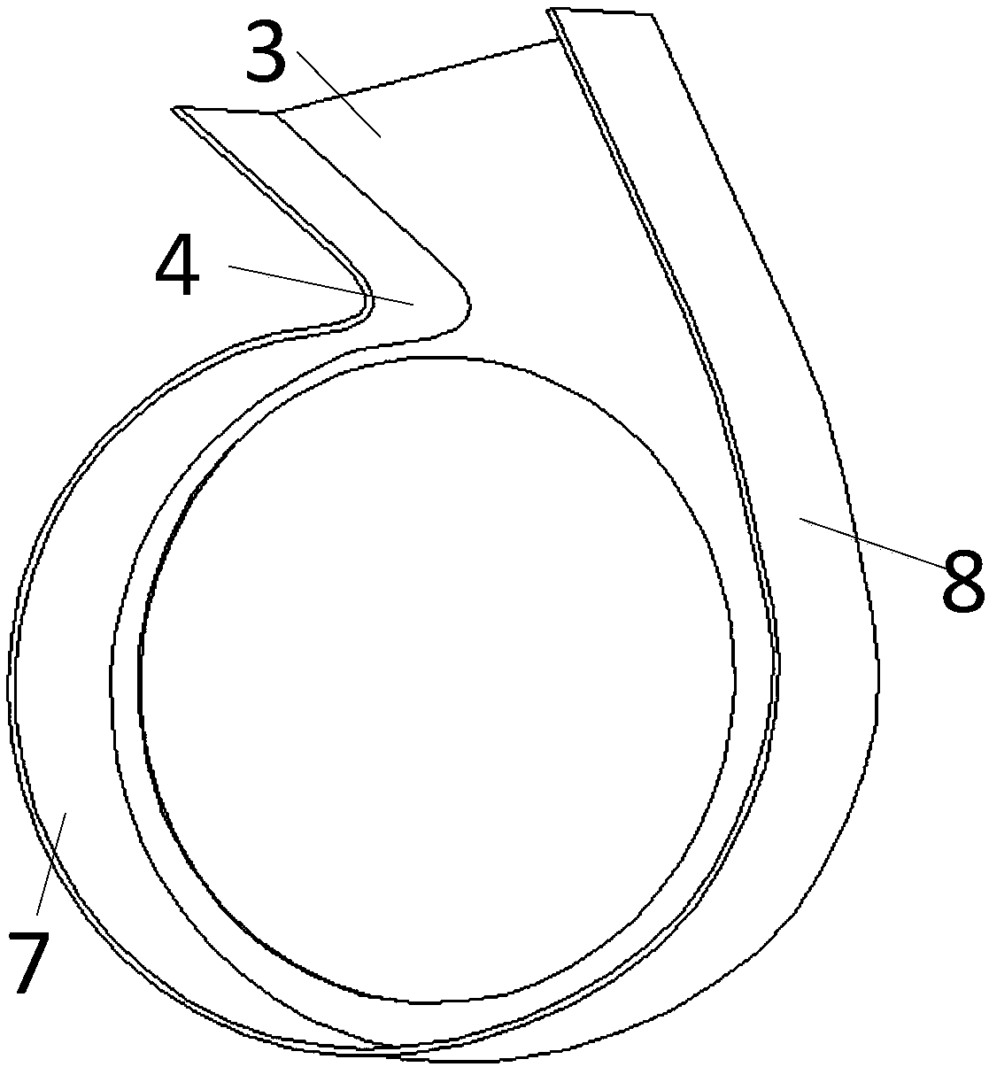
technical field [0001] The invention relates to the technical field of volute structures, in particular to a stepped volute and a centrifugal fan and blower comprising the same. Background technique [0002] The centrifugal fan provided in the prior art, such as figure 1 As shown, the shapes of the volute tongue and the diffuser section are usually the same structural line in the direction from the front disk 7 of the blade to the rear disk 8 of the blade, or there is little change. According to the airflow law of the centrifugal fan, the airflow gathers less at the front disk of the fan blade, and the airflow velocity from the blades near the front disk of the fan blade is relatively low. In addition, the distance from the volute tongue 4 is relatively long, and when the airflow flows to the volute tongue, the impact force is insufficient, and the separation and diversion cannot be effectively performed. [0003] During operation, the backflow of the airflow is often gene...

Claims


Application Information

Patent Timeline
Patent Type & Authority Applications(China)
IPC IPC(8): F04D29/42F04D29/66
CPCF04D29/422F04D29/4226F04D29/667
Inventor 李建建吴俊鸿
Owner GREE ELECTRIC APPLIANCES INC
Why Eureka
Try Eureka