
Special gear acceleration assembly connecting shaft

A technology for connecting shafts and gears, applied in the direction of belts/chains/gears, shafts, couplings, etc., can solve the problems of safety, stability, safety hazards, determining service life, shortening service life, etc., and achieve good overall structural strength, Safety and Stability Reliable Effects

Inactive Publication Date: 2018-08-24
丁涌
View PDF0 Cites 0 Cited by
  • Summary
  • Abstract
  • Description
  • Claims
  • Application Information

AI Technical Summary

Problems solved by technology

The traditional gear structure is assembled and connected through the central connecting shaft during assembly and use. Its connection structure is relatively simple, and the stability of the connection is relatively poor. For some structures with relatively fast rotation speeds, safety and stability become a serious safety issue. Hidden dangers, which determine the service life of the gear structure during use
During the rotation of the gear structure, especially in the process of high-speed rotation, the air around the gear structure will generate a vortex, which can have a certain impact on the assembly and connection structure of the gear. Although this impact is relatively small, it can be used for a long time. It will shorten its service life and reduce the rotation accuracy during use

Method used


Image

  • Special gear acceleration assembly connecting shaft
  • Special gear acceleration assembly connecting shaft
  • Special gear acceleration assembly connecting shaft

Examples


Embodiment Construction

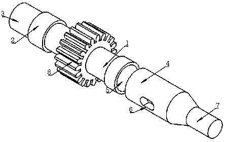
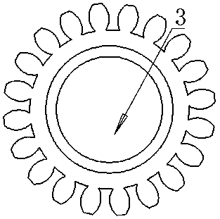
[0017] Such as Figure 1 to Figure 6 As shown, a special gear speed-up assembly connecting shaft, which can assemble two gear structures together at the same time. The central assembly hole of the center assembly and the assembly connection auxiliary support column of this part are connected and assembled together, which can meet the needs of a wider range of gear assembly, and the overall structural strength is better. The shock-absorbing assembly connection sealing ring is also installed between the two gears. The shock-absorbing treatment is performed on the middle position of the parts, so that the safety and stability of the gear assembly structure at each position are more reliable when used, and the safety of the high-speed rotating gear is more guaranteed when used, so that the use of the gear structure The scope is wider, and when this part is assembled with the mechanical structure, the assembly operation is more convenient through the positioning columns at both end...


PUM


Abstract

The invention relates to the technical field of gear structures, in particular to a special gear acceleration assembly connecting shaft. According to the adopted technical scheme, the special gear acceleration assembly connecting shaft comprises a cylindrical main body connecting supporting column, a cylindrical reinforcing connection stop column which is integrally formed is arranged on the leftside of the main body connecting supporting column, a cylindrical first assembly positioning column is arranged in the center of the left side of the reinforcing connection stop column, a cylindricalassembly connection assist supporting column which is integrally formed is arranged on the right side of the main body connecting supporting column, a damping assembly connection sealing ring is arranged at the position, close to the left side, of the external cylindrical surface of the assembly connection assist supporting column in a concentric distribution manner, the section of the damping assembly connection sealing ring is semicircular, and a second assembly positioning connecting hole is formed in the right front end of the external cylindrical surface of the assembly connection assistsupporting column. The special gear acceleration assembly connecting shaft has the advantages that safety and stability are higher when the shaft is in use, the safety of a gear rotating at a high speed in use is guaranteed better, and the application range of a gear structure is wider.

Description

technical field [0001] The invention relates to the technical field of gear structures, in particular to a special gear speed-up assembly connecting shaft. Background technique [0002] A gear is a mechanical element with teeth on the rim that can continuously mesh to transmit motion and power. It is a toothed mechanical part that can mesh with each other. The traditional gear structure is assembled and connected through the central connecting shaft during assembly and use. Its connection structure is relatively simple, and the stability of the connection is relatively poor. For some structures with relatively fast rotation speeds, safety and stability become a serious safety issue. Hidden dangers, it determines the service life of the gear structure during use. During the rotation of the gear structure, especially in the process of high-speed rotation, the air around the gear structure will generate a vortex, which can have a certain impact on the assembly and connection s...

Claims


Application Information

Patent Timeline
Patent Type & Authority Applications(China)
IPC IPC(8): F16C3/02F16D1/08F16H57/023F16F15/12
CPCF16C3/02F16D1/08F16D1/0876F16F15/1201F16H57/023
Inventor 丁涌
Owner 丁涌
Learn More