
Reverse suction air bearing structure

An air-bearing and air-bearing pad technology, applied in the directions of air-cushion bearings, bearings, shafts and bearings, can solve the problems of large motion inertia, large mass, additional disturbance of the spacecraft deployment mechanism, etc., to improve the reliability of the system, The effect of improving accuracy

Pending Publication Date: 2018-08-24
TIANJIN AEROSPACE ELECTROMECHANICAL EQUIP RES INST
View PDF0 Cites 6 Cited by
  • Summary
  • Abstract
  • Description
  • Claims
  • Application Information

AI Technical Summary

Problems solved by technology

[0002] Micro-low gravity simulation technology of spacecraft is a new field emerging with the development of space technology, and it is one of the main technologies that all space powers have paid attention to. The microgravity simulation methods include the suspension method, the suspension method commonly used brackets, gantry, swing arm and other structures. The movement of the mechanism creates a large additional disturbance, and the moment of inertia is large, which affects the deployment accuracy. Therefore, in the microgravity simulation method of the suspension method, how to reasonably provide a structure suitable for hoisting has become another research topic.

Method used


Image

  • Reverse suction air bearing structure
  • Reverse suction air bearing structure

Examples


Embodiment Construction

[0023] It should be noted that, in the case of no conflict, the embodiments of the present invention and the features in the embodiments can be combined with each other.

[0024] In describing the present invention, it should be understood that the terms "center", "longitudinal", "transverse", "upper", "lower", "front", "rear", "left", "right", The orientations or positional relationships indicated by "vertical", "horizontal", "top", "bottom", "inner", "outer", etc. are based on the orientation or positional relationships shown in the drawings, and are only for the convenience of describing the present invention Creation and simplification of description, rather than indicating or implying that the device or element referred to must have a specific orientation, be constructed and operate in a specific orientation, and therefore should not be construed as limiting the invention. In addition, the terms "first", "second", etc. are used for descriptive purposes only, and should no...


PUM


Abstract

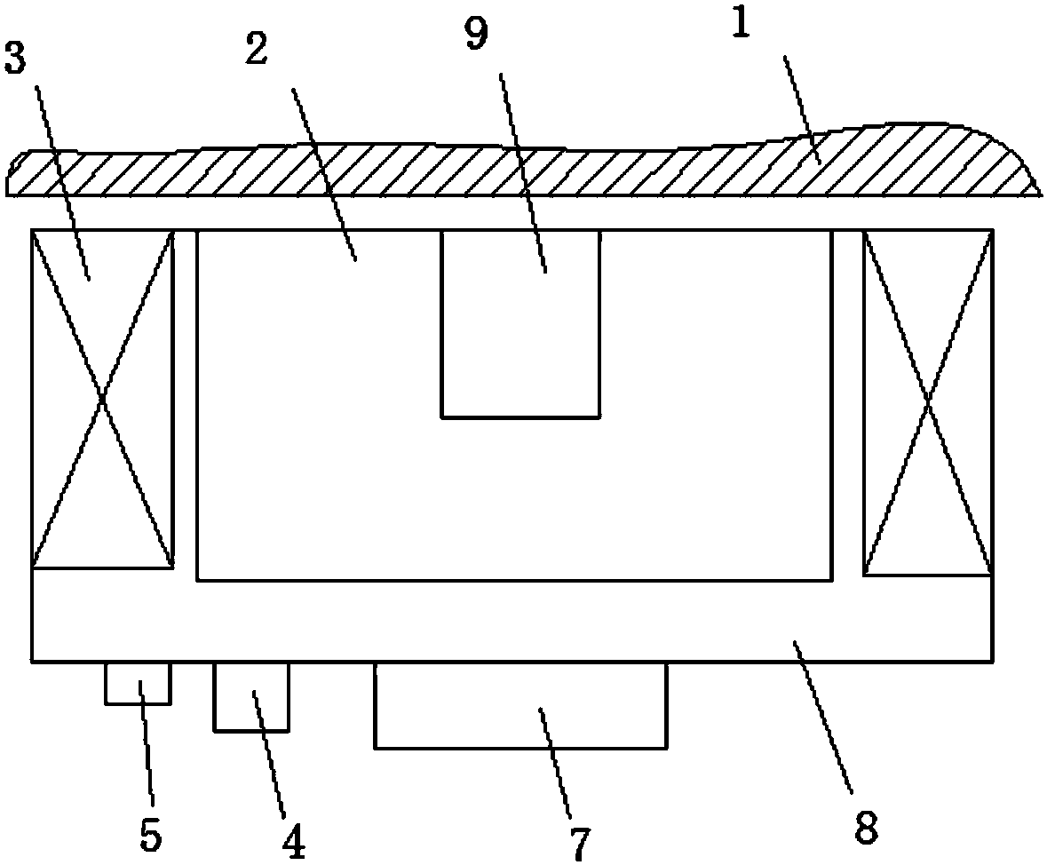
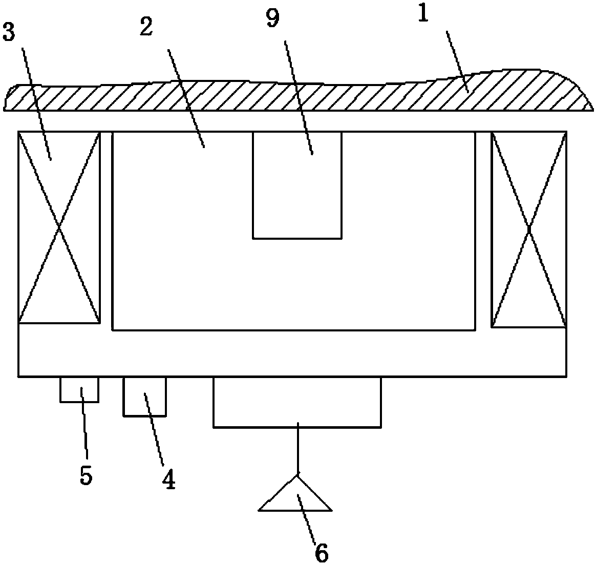
The invention provides a reverse suction air bearing structure. The structure comprises an air floatation pad, and a permanent magnet and electromagnets that are arranged on the air floatation pad. Vent holes of the air floatation pad are disposed on the top surface, a concave part is disposed at the center of the air floatation pad top surface, and the permanent magnet is embedded in the concavepart. The reverse suction air bearing structure provided by the invention combines the air flotation technology and electromagnetic technology, during use, the reverse suction air bearing is adsorbedunder a magnetic conductive panel, suspension force is generated by electromagnetic force to achieve balance with the resultant force of an air flotation unit's air flotation force and a hanging load,a hanging point can realize frictionless two-dimensional movement along the bottom of the magnetic conductive panel at the top, and frictionless non-contact free movement in the plane, and the accuracy of microgravity simulation and the system reliability are improved.

Description

technical field [0001] The invention belongs to the field of equipment for simulating microgravity by the suspension method, and in particular relates to a suction-back type air bearing structure. Background technique [0002] Micro-low gravity simulation technology of spacecraft is a new field emerging with the development of space technology, and it is one of the main technologies that all space powers have paid attention to. The microgravity simulation methods include the suspension method, the suspension method commonly used brackets, gantry, swing arm and other structures. The movement of the mechanism creates a large additional disturbance, and the moment of inertia is large, which affects the deployment accuracy. Therefore, in the microgravity simulation method of the suspension method, how to reasonably provide a structure suitable for hoisting has become another research topic. Contents of the invention [0003] In view of this, the present invention aims to prop...

Claims


Application Information

Patent Timeline
Patent Type & Authority Applications(China)
IPC IPC(8): F16C32/06
CPCF16C32/0603
Inventor 齐放李鹏赵宝山李跃华
Owner TIANJIN AEROSPACE ELECTROMECHANICAL EQUIP RES INST
Learn More