Worm and gear speed reducer

A technology of worm reducer and worm gear, which is applied in the direction of gear transmission, belt/chain/gear, transmission parts, etc., to achieve the effect of large torque

Inactive Publication Date: 2018-08-24
重庆东渝中能实业有限公司
View PDF6 Cites 1 Cited by
  • Summary
  • Abstract
  • Description
  • Claims
  • Application Information

AI Technical Summary

Problems solved by technology

[0004] However, the current worm gear reduc

Method used


Image

  • Worm and gear speed reducer
  • Worm and gear speed reducer
  • Worm and gear speed reducer

Examples


Embodiment

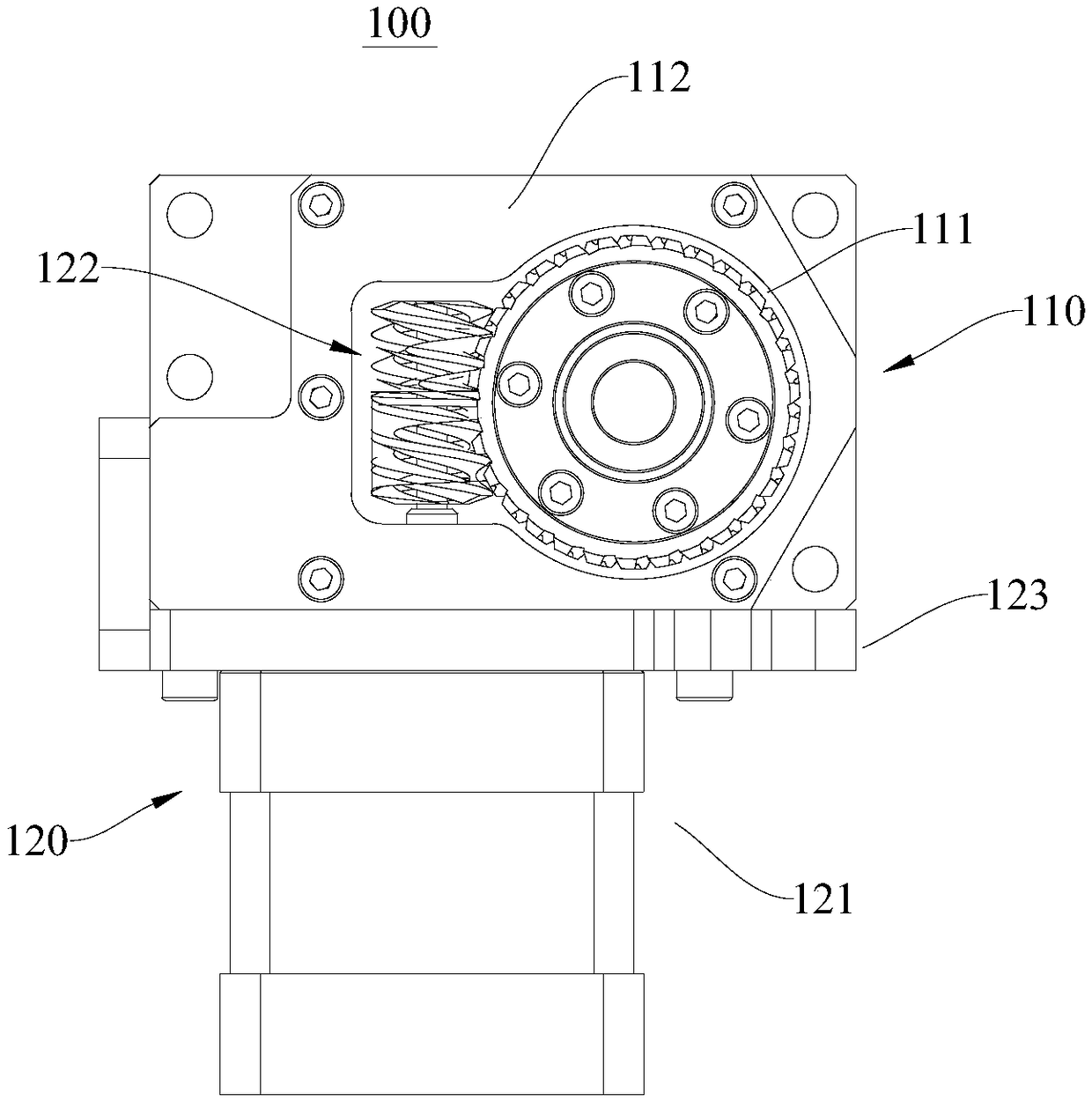
[0041] This embodiment provides a worm gear reducer 100, please refer to figure 1 .

[0042] The worm gear reducer 100 includes a worm gear assembly 110 and a worm assembly 120 .

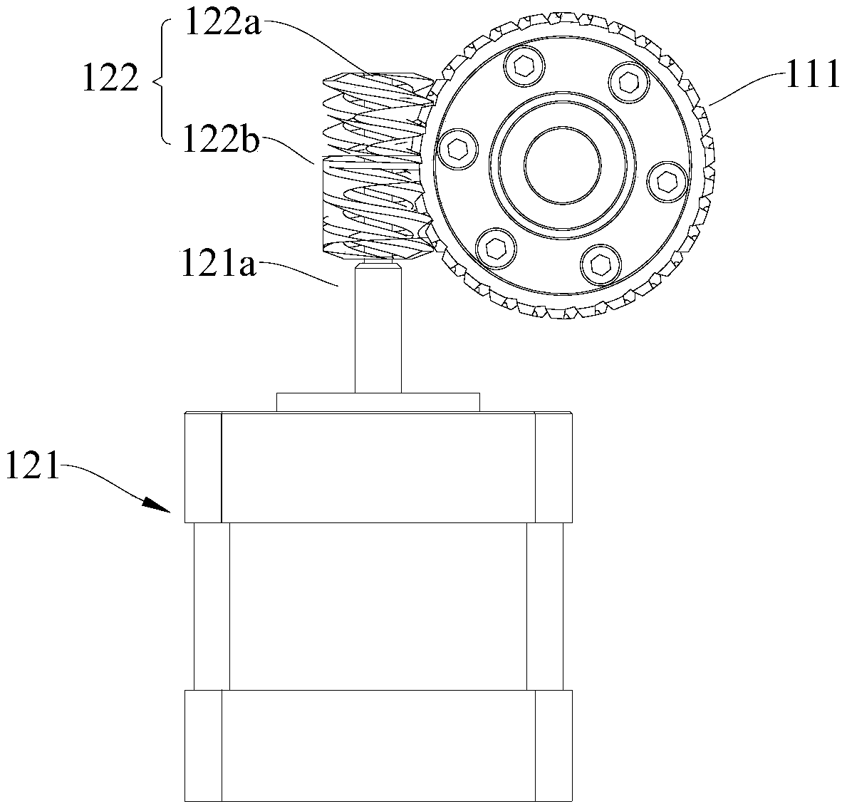
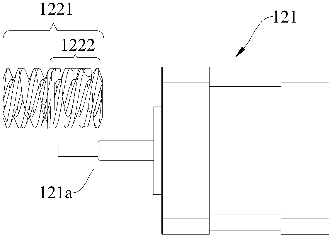
[0043] Please refer to figure 1 and figure 2 , wherein the worm gear assembly 110 includes a worm gear 111 . The worm assembly 120 includes a worm 122 that can mesh with the worm gear 111 and a motor 121 that drives the worm 122 to rotate. The motor 121 includes a power output shaft 121a. The power output shaft 121a of the motor 121 is in drive connection, and the helical teeth 122b extend toward the power output shaft 121a and cover the power output shaft 121a.

[0044] When in use, the motor 121 drives the worm 122 to rotate axially along its wheel shaft 122a. When the worm 122 rotates, the helical teeth 122b on the wheel shaft 122a mesh with the worm wheel 111 to drive the worm wheel 111 to rotate. The worm gear reducer 100 utilizes the speed conversion of the gears to reduce the number of ...


PUM


Abstract

The invention provides a worm and gear speed reducer, and belongs to the technical field of speed reducers. The worm and gear speed reducer comprises a worm gear assembly and a worm assembly; the wormgear assembly comprises a worm gear; the worm assembly comprises a worm and a motor, wherein the worm can mesh with the worm gear, and the motor drives the worm to rotate; the motor comprises a poweroutput shaft; the worm comprises a wheel shaft and spiral teeth, wherein the spiral teeth are arranged in the circumferential direction of the wheel shaft; the wheel shaft is in transmission connection with the power output shaft of the motor; and the spiral teeth extend to the power output shaft and cover the power output shaft. According to the worm and gear speed reducer, the defect of large transmission error can be overcome.

Description

technical field [0001] The present invention relates to the technical field of reducers, in particular to a worm gear reducer. Background technique [0002] At present, the worm gear reducer is a power transmission mechanism that uses the speed conversion of the gear to reduce the number of revolutions of the motor or motor to the desired number of revolutions and obtain a larger torque mechanism. [0003] Worm gear reducers are used in a wide range of applications, from ships, automobiles, locomotives, heavy machinery for construction, processing machinery and automated production equipment used in the machinery industry, to common household appliances, clocks and watches in daily life. Its application can be seen in the application of reducer from the transmission work of large power to small load and precise angle transmission. [0004] However, the current worm gear reducer has a large transmission error during use. Contents of the invention [0005] The purpose of t...

Claims


Application Information

Patent Timeline
IPC IPC(8): F16H1/16F16H57/023
CPCF16H1/16F16H57/023
Inventor 梁惺江世欢查沛
Owner 重庆东渝中能实业有限公司
Why Eureka
Try Eureka