Vertical transmission method of gearbox for rail transit and vertical transmission gearbox

A rail transit and gear box technology, applied in transmission boxes, transmission parts, gear lubrication/cooling, etc., can solve the problem that the traction motor and gear box have no installation location, the gearbox and traction motor have no installation space, and the traction motor and gear The installation space of the box is small and other problems, so as to achieve the effect of saving installation space, compact structure and small volume.

Pending Publication Date: 2018-08-24
株洲九方装备驱动技术有限公司 +1
View PDF8 Cites 1 Cited by
  • Summary
  • Abstract
  • Description
  • Claims
  • Application Information

AI Technical Summary

Problems solved by technology

[0007] The present invention aims at the problem that the current gear box is too large to adapt to the compact structure of the rail vehicle bogie, and the installation space of the traction motor and the gear box is narrow, resulting in no installation position for the traction motor and the gear box. The transmission method and vertical transmission gearbox are designed to solve the problem of no installation space for gearboxes and traction motors in some cases, and also provide a new solution for the arrangement of gearboxes and traction motors in order to meet the diversified development needs of rail transit equipment The scheme changes the arrangement relationship between the traditional gearbox and the motor

Method used


Image

  • Vertical transmission method of gearbox for rail transit and vertical transmission gearbox
  • Vertical transmission method of gearbox for rail transit and vertical transmission gearbox
  • Vertical transmission method of gearbox for rail transit and vertical transmission gearbox

Examples


Embodiment 1

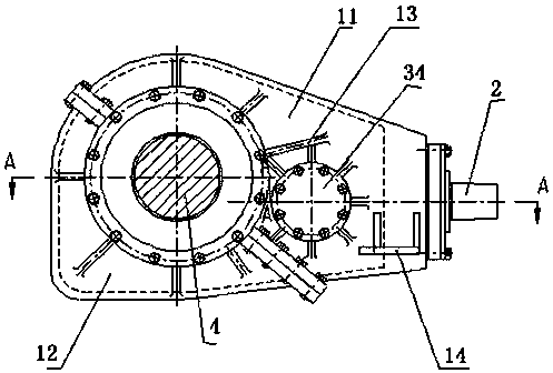
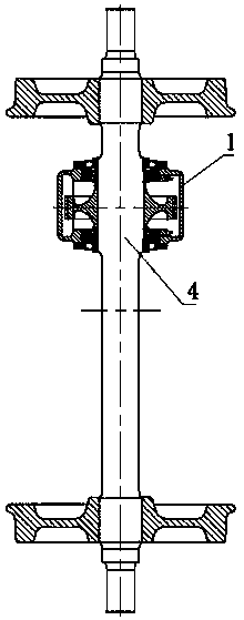
[0038] Such as Figure 1-3 As shown, a vertical transmission gearbox for rail transit adopts a two-stage transmission mode, including a gear box body 1, the gear box body 1 is used as the installation main body, and a fixing device is arranged inside, and the transmission device is installed on the gear box through the fixing device Body 1. Transmit the movement of the traction motor to the axle to drive the train forward. The fixing device includes an input fixing device, an intermediate fixing device and an output fixing device, and the input shaft, the intermediate shaft and the output shaft are mounted on the gear case 1 through the fixing device, the intermediate fixing device and the output fixing device respectively.

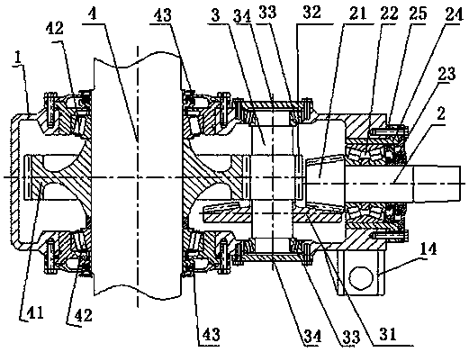
[0039] The input fixing device includes an input bearing seat and an input bearing arranged in the input bearing seat. The input bearing is installed on the end of the gearbox body 1 through the input bearing seat. The input shaft 2 passes through the hole ...

Embodiment 2

[0044] Such as figure 2 As shown, in this embodiment, an oil collecting tank and a lubricating oil passage are provided in the gear box body 1, and the gears and bearings are lubricated by splash lubrication to ensure that each gear and bearings are sufficiently lubricated.

Embodiment 3

[0046] Such as figure 2 As shown, in this embodiment, the bearing bush and the end face of the gear box 1 are provided with an adjusting pad 25, which can precisely adjust the axial position of the input shaft 2, thereby adjusting the bevel gear backlash of the first-stage transmission, so that Bevel gear one 21 and bevel gear two 31 are in the best meshing state.


PUM


Abstract

The invention provides a vertical transmission method of a gearbox for rail transit and a vertical transmission gearbox. An input shaft and an output shaft are vertically arranged, a second-stage transmission mode is adopted for transmitting the rotation of the input shaft to the output shaft through vertical transmission, a first-stage transmission device transmits the rotation of the input shaftto a middle shaft in a vertical transmission mode, and a second-stage transmission device transmits the rotation of the middle shaft to the output shaft in a parallel transmission mode. The second-stage transmission mode is adopted, the first-stage transmission device adopts vertical transmission, and the second-stage transmission device adopts parallel transmission, so that the size of the wholegearbox is small, the structure is compact, and the installation space is greatly saved. The two-stage transmission enables the transmission ratio to be adjusted within a larger range, and is high inreliability.

Description

technical field [0001] The invention relates to a gear box transmission method and the gear box, in particular to a rail transit gear box vertical transmission method and the vertical transmission gear box. Background technique [0002] The gearbox is the core component of the vehicle transmission system of rail transit equipment. It is generally installed on the axle, and the other end is suspended on the frame through the boom, and the input torque of the traction motor is transmitted to the wheel set through a certain transmission ratio, which is safe and reliable for the operation of the vehicle. Sex matters. [0003] The traditional gearbox transmission method is generally one-stage or two-stage parallel gear shaft transmission, and the traction motor shaft is also parallel to the gear shaft, and is installed between the axle and the middle beam. Due to the compact structure of the bogie, the installation space of the traction motor and the gearbox is very limited. Whe...

Claims


Application Information

Patent Timeline
Patent Type & Authority Applications(China)
IPC IPC(8): F16H57/022F16H57/023F16H57/029F16H57/03F16H57/038F16H57/04
CPCF16H57/022F16H57/023F16H57/029F16H57/03F16H57/038F16H57/0424F16H2057/02086F16H2057/02052F16H2057/02034
Inventor 陈宇向姜宇飞刘领化潘喻夏从焱周桂林
Owner 株洲九方装备驱动技术有限公司
Why Eureka
Try Eureka