Self-locking valve

A technology of self-locking valve and valve body, which is applied in the direction of lifting valve, valve details, valve device, etc., can solve the problem of low consistency of action, and achieve the effect of realizing intelligent control, ensuring accuracy and ensuring precision

Active Publication Date: 2019-11-08
HENAN AEROSPACE HYDRAULIC & PNEUMATIC TECH
View PDF5 Cites 0 Cited by
  • Summary
  • Abstract
  • Description
  • Claims
  • Application Information

AI Technical Summary

Problems solved by technology

[0006] The purpose of the present invention is to provide a self-locking valve, which can solve the problem of low action consistency between the valve stem and the armature in the prior art

Method used


Image

  • Self-locking valve
  • Self-locking valve
  • Self-locking valve

Examples


Embodiment Construction

[0030] Embodiments of the present invention will be further described below in conjunction with the accompanying drawings.

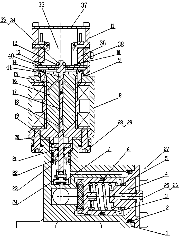
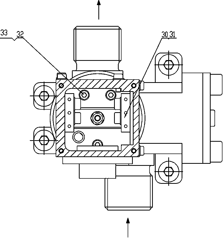
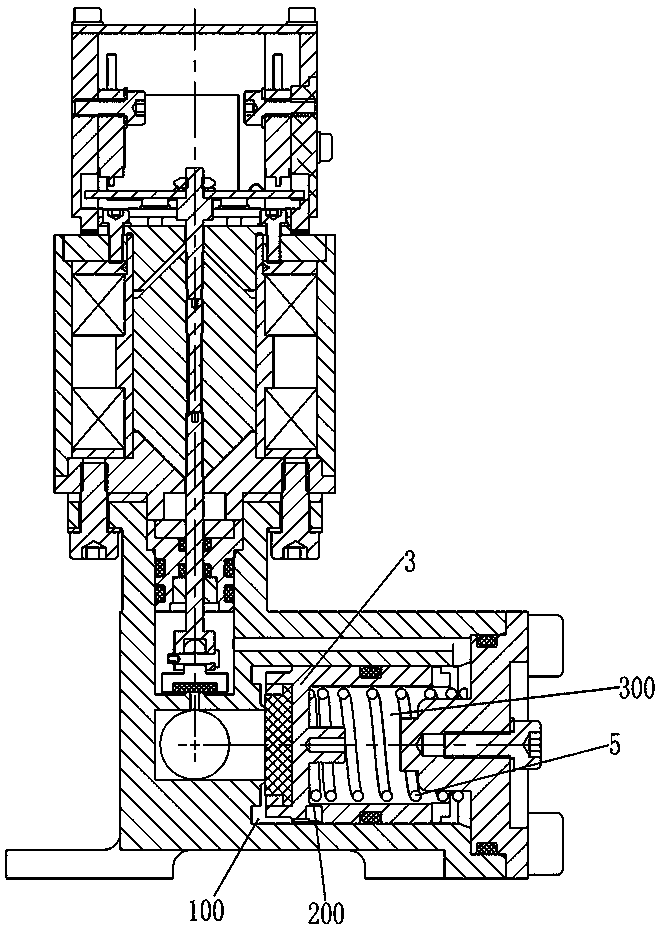
[0031] The specific embodiment of self-locking valve provided by the present invention, as Figure 1 to Figure 3 As shown, the self-locking valve in this embodiment includes a main valve and an electromagnet 8, and the electromagnet 8 is fixedly installed on the valve body of the main valve through a small washer B28 and a hexagonal cylinder head screw B29, and, in the armature 16, a The mounting hole extending in the direction of reciprocating movement of the armature 16, the valve stem 18 of the self-locking valve is fastened and assembled in the mounting hole through a threaded connection. Since the valve stem 18 forms an integral structure with the armature through a threaded connection, it can drive the armature 16 when it moves. The valve stem 18 acts synchronously, which ensures the consistent action between the armature 16 and the valve stem 18 ....


PUM


Abstract

The invention provides a self-locking valve. The self-locking valve comprises a valve body with an inlet and an outlet; a main channel is arranged in the valve body and provided with a main valve seat; the main channel comprises an inlet side and an outlet side which are located on the two sides of the main valve seat; a main valve element matched with the main valve seat is arranged on the inletside of the valve body; the valve body is internally provided with a reset spring for applying action force on the main valve element to force the main valve element to be closed and further providedwith a back pressure cavity; the back pressure cavity communicates with the outlet side through a control channel; the control channel is internally provided with a control valve seat and a corresponding control valve element; the valve body is provided with an electromagnet used for driving the control valve element to act; the electromagnet comprises an armature and a valve rod arranged on the armature; the armature is provided with a mounting hole extending in the reciprocating moving direction of the armature; and the valve rod is connected, fastened and assembled in the mounting hole through threads.

Description

technical field [0001] The invention relates to the technical field of valves, in particular to a self-locking valve. Background technique [0002] According to its different structures, the valve can realize the functions of pressure regulation, reversing, on-off and so on. When the valve controls the relevant liquid or gas circuit to be conducted or disconnected, the valve core moves. When the valve core contacts and seals with the corresponding valve port, the valve closes and the corresponding liquid or gas circuit is disconnected. When the corresponding valve port is disengaged, the valve is opened, and the corresponding liquid or gas circuit is conducted. [0003] In the patent of invention CN85201792, a multifunctional solenoid valve is disclosed. This multifunctional solenoid valve is actually equipped with a solenoid valve that plays a control role on the on-off main valve. The main valve includes a valve with an inlet and an outlet. The valve body is provided wit...

Claims


Application Information

Patent Timeline
Patent Type & Authority Patents(China)
IPC IPC(8): F16K31/06F16K1/32F16K1/36F16K1/14
CPCF16K1/14F16K1/32F16K1/36F16K31/0655F16K31/0662F16K31/0675
Inventor 荆兵张启明苏征冯茜张建刚王梅平黄娟吕千里尚鑫黄世鹏
Owner HENAN AEROSPACE HYDRAULIC & PNEUMATIC TECH
Why Eureka
Try Eureka