Self-adaptive sensing system and method based on liquid crystal beam expanding photoelectric device

A technology for optoelectronic devices and sensing systems, applied in the field of 3D sensing, can solve the problems of restricting the development of full-screen mobile phones, large space and complex structure, and achieve the effects of structural integration, reduction of switching frequency, and reduction of power consumption.

Pending Publication Date: 2022-05-06
重庆晶朗光电有限公司
View PDF0 Cites 0 Cited by
  • Summary
  • Abstract
  • Description
  • Claims
  • Application Information

AI Technical Summary

Problems solved by technology

[0004] At present, the infrared / 3D cameras on the market, such as the infrared 3D cameras used by the FaceID face recognition camera module, mostly use dual light source or multi-light source structure sampling mode, which captures information such as contour and depth respectively, and then realizes 3D shooting through data integration. Complex structure and high cost
Therefore, the infrared light source structure module of the existing structured light solution requires a total of two sets of VCSEL lasers. The cost is relatively high and the space volume is large. In products with limited volume such as mobile phones, the space of the non-display area above the screen will be increased. (Usually referred to as "notch area"), restricting the development of full-screen mobile phones, whether it is from the perspective of trends or aesthetics, the demand for module miniaturization, low cost, and low power consumption is imperative

Method used


Image

  • Self-adaptive sensing system and method based on liquid crystal beam expanding photoelectric device
  • Self-adaptive sensing system and method based on liquid crystal beam expanding photoelectric device
  • Self-adaptive sensing system and method based on liquid crystal beam expanding photoelectric device

Examples


Embodiment Construction

[0044] The present invention is described in further detail now in conjunction with accompanying drawing.

[0045] It should be noted that terms such as "upper", "lower", "left", "right", "front", and "rear" quoted in the invention are only for clarity of description, not for Limiting the practicable scope of the present invention, and the change or adjustment of the relative relationship shall also be regarded as the practicable scope of the present invention without substantive changes in the technical content.

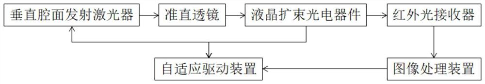
[0046] figure 2 It is a structural schematic diagram of an adaptive sensing system based on a liquid crystal beam expander optoelectronic device of the present invention. see figure 2 , the adaptive sensing system includes a vertical cavity surface emitting laser, a collimating lens, a liquid crystal beam expanding optoelectronic device, an adaptive driving device, an image processing device and an infrared light receiver.

[0047] The liquid crystal beam expan...


PUM


Abstract

The invention discloses a self-adaptive sensing system based on a liquid crystal beam expanding photoelectric device. The self-adaptive sensing system comprises a vertical cavity surface emitting laser, a collimating lens, the liquid crystal beam expanding photoelectric device, a self-adaptive driving device, an image processing device and an infrared light receiver, a laser beam emitted by the vertical cavity surface emitting laser is converted into collimated light through the collimating lens, the collimated light is irradiated to the DOE light diffraction layer in parallel, and the liquid crystal box is switched into an emptying state or a diffusion state with different haze levels under the control of a pulse signal output by the self-adaptive driving device. Diffracted light output by the DOE light diffraction layer is converted into corresponding projection dot matrix light spots or beam-expanded floodlight, and the surface of an object to be detected is irradiated with the corresponding projection dot matrix light spots or beam-expanded floodlight; and the infrared light receiver receives feedback light reflected by the surface of the object to be detected. According to the invention, electric control can be switched between floodlight scattering and light spot projection, two paths of infrared emission light sources are changed into a single path of light source, the size is saved, and the cost is reduced.

Description

technical field [0001] The invention relates to the technical field of 3D sensing, in particular to an adaptive sensing system and method based on a liquid crystal beam expander optoelectronic device. Background technique [0002] In recent years, 3D camera, 3D face recognition and 3D display have been widely used in more and more fields, and various 3D technologies and product markets are becoming more and more popular. 3D technology is a necessary sensor technology in the field of artificial intelligence. , After years of basic technology and application development, it began to develop rapidly. 3D sensors have great potential in artificial intelligence applications. At present, only 2D high-speed cameras can be used to collect plane video data. 2D data processing and analysis are not only large in volume but also low in accuracy. The combination of 3D sensing and optical markers can significantly improve timeliness, convenience, data integrity and accuracy. has been gre...

Claims


Application Information

Patent Timeline
Patent Type & Authority Applications(China)
IPC IPC(8): G02F1/13G02F1/1334G02F1/1335G06T7/00G01B11/24
CPCG02F1/1313G02F1/1309G02F1/13345G02F1/133504G01B11/24G06T7/0002G06T2207/10048G06T2207/10028G06T2207/10021
Inventor 周盼华董守亮
Owner 重庆晶朗光电有限公司
Why Eureka
Try Eureka