Reinforced concrete ejection pipe joint connector

A technology of reinforced concrete and pipe joints, which is applied in the direction of pipe/pipe joint/fitting, sleeve/socket connection, passing components, etc., which can solve the large load effect of the steel collar of the pipe joint socket and the uneven pressure of the sealing rubber ring , hindering the pipe joint jacking construction and other problems, to achieve the effect of improving the sealing performance, strengthening the effect of sealing and anti-seepage, and increasing the contact pressure

Active Publication Date: 2018-08-24
FOSHAN POWER SUPPLY BUREAU GUANGDONG POWER GRID +2
View PDF6 Cites 4 Cited by
  • Summary
  • Abstract
  • Description
  • Claims
  • Application Information

AI Technical Summary

Problems solved by technology

Electric pipe jacking construction has high requirements on the waterproof performance of pipe joints, but in many engineering projects, pipe joints leak water.
Especially in weak formations with high water pressure, traditional wedge-shaped rubber rings or O-rings cannot withstand sufficient water pressure to achieve a complete sealing effect. wedge rubber ring
In addition, due to the uneven settlement of the pipeline, on the one hand, it is easy to cause the uneven pressure of the sealing rubber ring, which weakens its sealing effect; Ring deformation hinders pipe joint jacking construction

Method used


Image

  • Reinforced concrete ejection pipe joint connector
  • Reinforced concrete ejection pipe joint connector
  • Reinforced concrete ejection pipe joint connector

Examples


Embodiment Construction

[0025] The present invention will be described in detail below in conjunction with the accompanying drawings and embodiments, and the content of the present invention is not limited to the following embodiments.

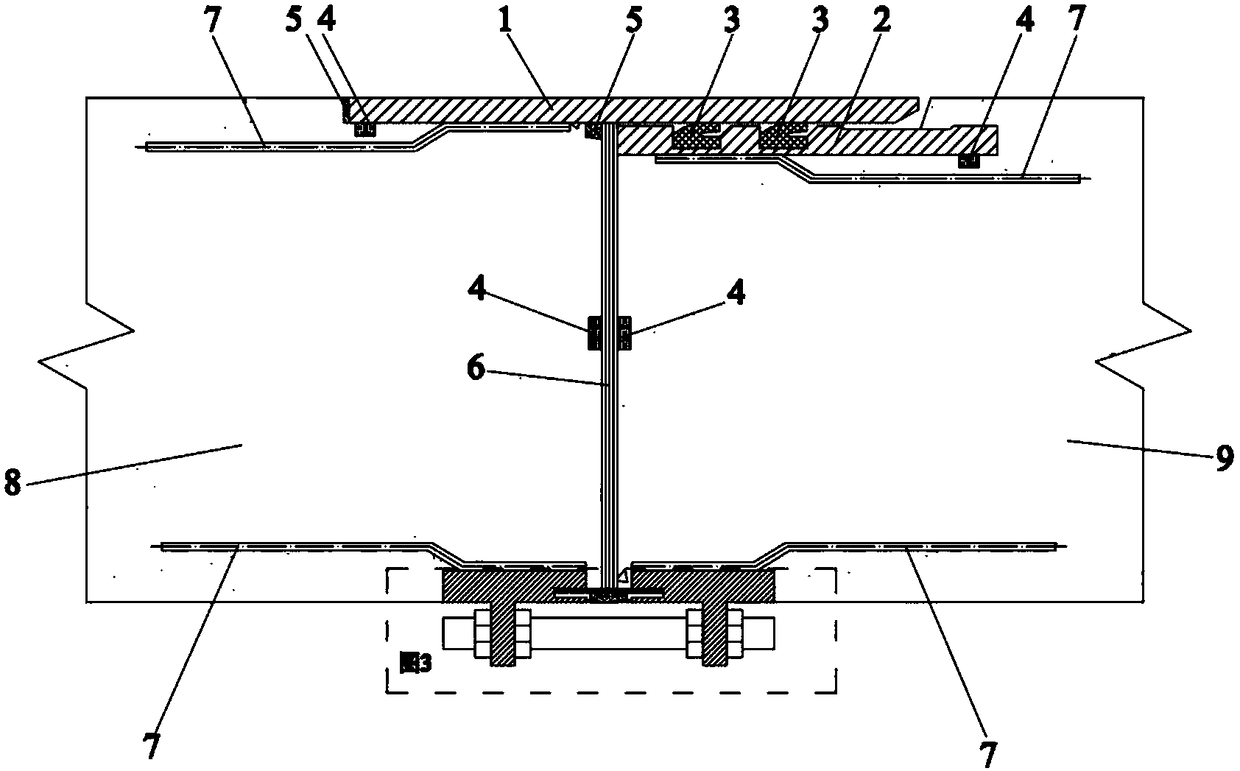
[0026] The reinforced concrete pipe jacking pipe joint provided by the invention is located at the interface between the adjacent front pipe joint and the rear pipe joint, and the pipe joint is fully sealed from the outer wall of the pipe joint, the contact section of the pipe joint and the inner wall of the pipe joint. The pipe joint outer wall sealing connection part and the pipe joint inner wall sealing connection part connect the pipe joints. The pipe joints and pipe joint joints are ring-shaped as a whole. figure 1 Shown in is a cross-sectional schematic diagram of the uppermost part of a reinforced concrete pipe jacking pipe joint and the front and rear pipe wall. .

[0027] The reinforced concrete pipe jacking joint is located at the interface between the ad...


PUM


Abstract

The invention relates to the technical field of ejection pipes of non-excavation works, in particular to a reinforced concrete ejection pipe joint connector. The connector is positioned at a connection between a front pipe joint and a rear pipe joint which are adjacent. The connection part of the connector at least comprises a pipe joint outer wall sealing connecting part and a pipe joint inner wall sealing connecting part. The pipe joint outer wall sealing connecting part at least comprises a socket steel bushing ring positioned at the rear end of the front pipe joint and a socket steel ringpositioned at the front end of the rear pipe joint. The pipe joint inner wall sealing connecting part at least comprises the structure that steel bushing rings separately arranged on the front pipe joint inner wall and the rear pipe joint inner wall. Each steel bushing ring at least comprises an annular steel ring and an annular slab. Ribbed plates and bolted holes are uniformly distributed on thefront side and the rear side of the slab. The ribbed plate and the bolted holes are staggered mutually in position. The bolted holes in the front pipe joint slab are corresponding to those of the rear pipe joint slab. The bolted holes corresponding to one another are connected by bolts and nuts. The pipe joint connector adopting the technical scheme can completely meet the need of projects with high waterproof requirements, and can adapt to complex construction environments such as high water pressure and soft ground.

Description

technical field [0001] The invention relates to the technical field of trenchless engineering pipe jacking, in particular to reinforced concrete pipe jacking joint joints. Background technique [0002] In recent years, with the acceleration of social modernization, trenchless technology, especially pipe jacking technology, has been rapidly promoted and applied. Pipe jacking technology is widely used in the field of municipal engineering, in which electric power pipe jacking is used for the underground laying of cables, mainly large-diameter reinforced concrete pipes, and the interface form is mainly F-shaped steel sockets. Electric pipe jacking construction has high requirements on the waterproof performance of pipe joints, but in many engineering projects, water leakage occurs in pipe joints. Especially in weak formations with high water pressure, traditional wedge-shaped rubber rings or O-rings cannot withstand sufficient water pressure to achieve a complete sealing effec...

Claims


Application Information

Patent Timeline
Patent Type & Authority Applications(China)
IPC IPC(8): F16L21/08
CPCF16L21/08
Inventor 胡晓萌欧繁陈洪海屈勇苏波王乐天姚积坤罗向源张虎张俊宋丽敏唐取曾川峰柳春芳张栋曾昭贵梁唐杰任坤邬彪彪傅志浩季严飞贾福东陈晓龙
Owner FOSHAN POWER SUPPLY BUREAU GUANGDONG POWER GRID
Why Eureka
Try Eureka