A single-degree-of-freedom optical detection platform driven by piezoelectricity and its application method

A driving platform and optical detection technology, applied in the direction of material analysis, measuring devices, scientific instruments, etc. through optical means, can solve the problems of axis deviation, poor positioning accuracy and reliability, low response speed and resolution of optical detection platform, etc.

Active Publication Date: 2020-07-07
SUZHOU RES INST SHANDONG UNIV
View PDF12 Cites 0 Cited by
  • Summary
  • Abstract
  • Description
  • Claims
  • Application Information

AI Technical Summary

Problems solved by technology

[0004] However, the disadvantage of the existing optical detection platform is that there is no light hole required for detection in the center of the platform, and the sample needs to be fixed in the form of a cantilever, so that the axis of the sample is deviated from the axis of the platform, making its The positioning accuracy and reliability are poor, the closed platform is not conducive to the determination of sample dropping, and the existing optical detection platform has low response speed and resolution

Method used


Image

  • A single-degree-of-freedom optical detection platform driven by piezoelectricity and its application method
  • A single-degree-of-freedom optical detection platform driven by piezoelectricity and its application method
  • A single-degree-of-freedom optical detection platform driven by piezoelectricity and its application method

Examples


Embodiment Construction

[0029] It should be pointed out that the following detailed description is exemplary and intended to provide further explanation to the present application. Unless defined otherwise, all technical and scientific terms used herein have the same meaning as commonly understood by one of ordinary skill in the art to which this application belongs.

[0030] It should be noted that the terminology used here is only for describing specific implementations, and is not intended to limit the exemplary implementations according to the present application. As used herein, unless the context clearly dictates otherwise, the singular is intended to include the plural, and it should also be understood that when the terms "comprising" and / or "comprising" are used in this specification, they mean There are features, steps, operations, means, components and / or combinations thereof.

[0031] As described in the background technology, the existing optical detection platform has the disadvantage t...


PUM


Abstract

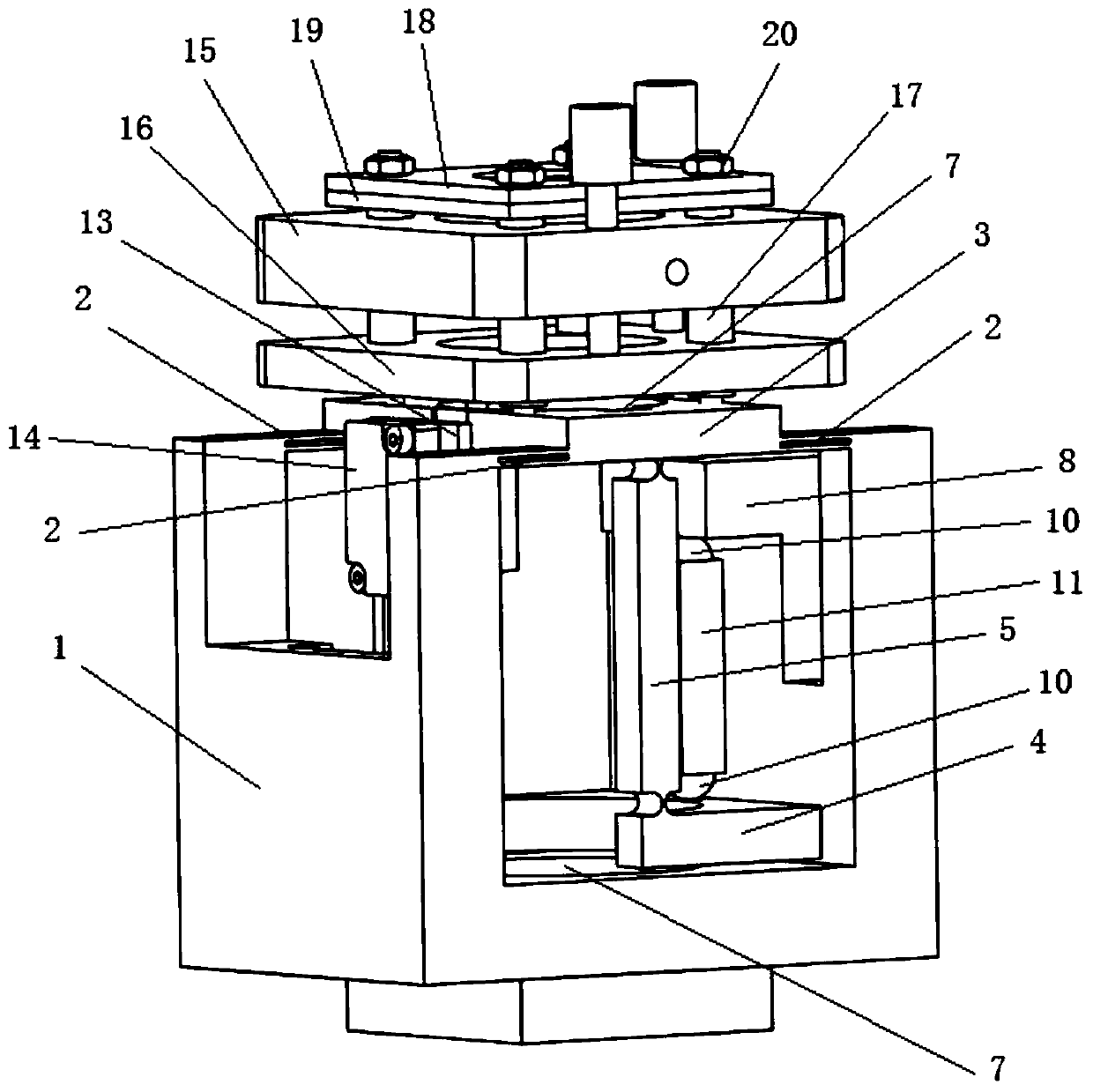
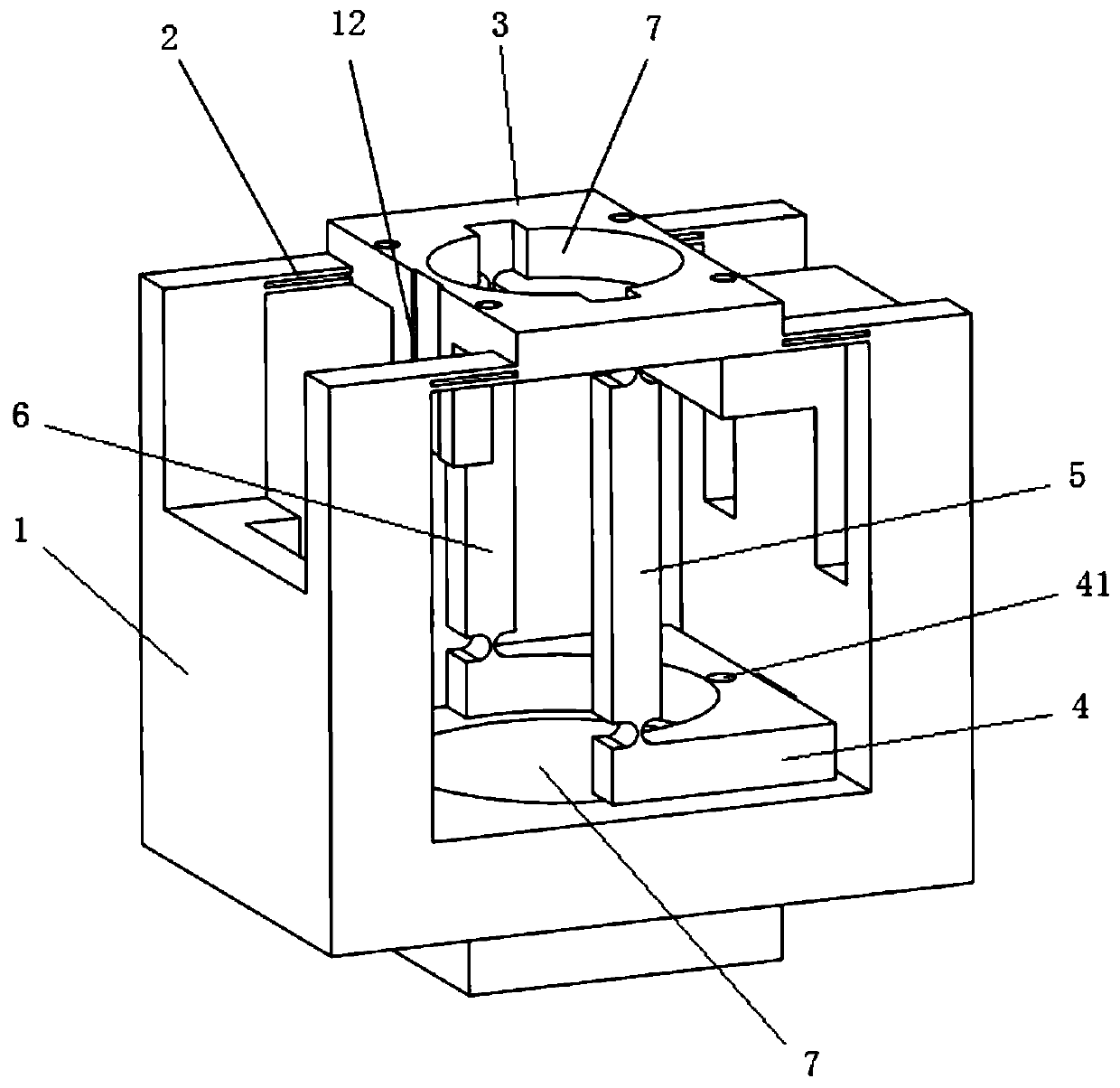
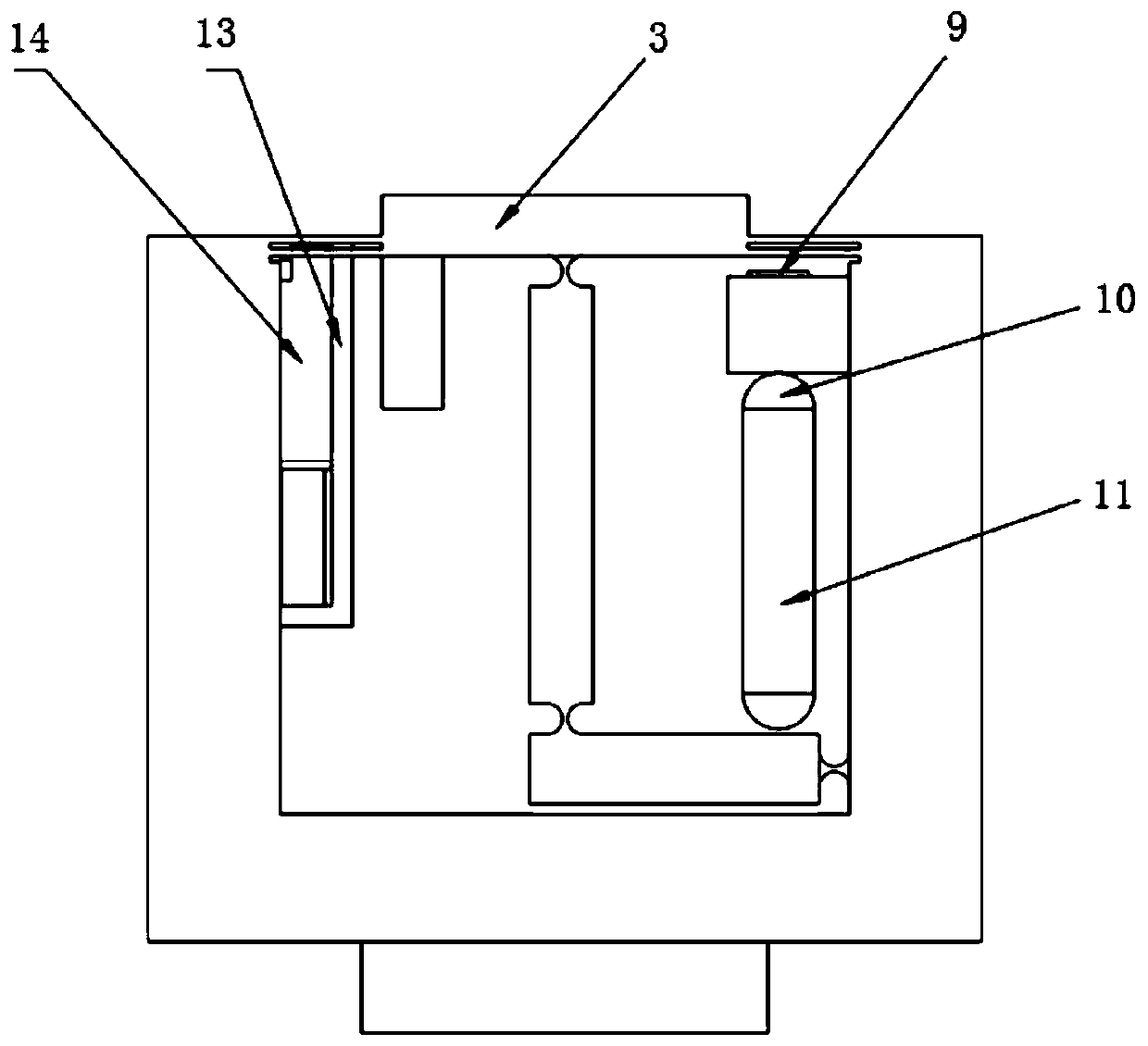
The invention relates to a piezoelectric-driving single-degree-of-freedom optical detection platform and a use method. The piezoelectric-driving single-degree-of-freedom optical detection platform comprises a driving platform, wherein the driving platform is of a hollow structure of which the upper part is provided with an opening; four leaf spring hinges are symmetrically distributed at the top end of the driving platform; one end of each of the four leaf spring hinges is connected with the driving platform, and the other ends of the four leaf spring hinges are connected with the four cornersof a tail platform; the bottom surface of the tail platform is connected with a lever amplifying mechanism in the hollow structure; the lever amplifying structure and the driving platform are respectively connected with both ends of the driving device; the telescopic deformation produced by the driving device is amplified by the lever amplifying mechanism, and is transferred to the tail platform,so that the tail platform can generate the displacement along the axial direction of the driving platform; concentric light through holes are formed in the center of the tail platform and the bottompart of the driving platform, a precise lens frame is arranged on the tail platform, and a detection mechanism is arranged at the side surface of the tail platform. The piezoelectric-driving single-degree-of-freedom optical detection platform has the advantages that the travel is large, the load capacity is strong, the resolution is high, the response speed is quick, and the operability is strong.

Description

technical field [0001] The invention relates to the technical field of optical detection equipment, in particular to a piezoelectric-driven single-degree-of-freedom optical detection platform and a use method thereof. Background technique [0002] Micro-nano technology is a high-tech technology focused on the development of countries in the world in the 21st century. Among them, the ultra-precise micro-nano positioning platform with nano-level positioning accuracy is the core power device of micro-nano technology. The ultra-precise micro-nano positioning platform has a wide range of applications in the field of precision optical engineering. [0003] The optical inspection platform is a key basic bearing device for installing optical inspection samples and test pieces. Its main function is to realize the stability and position adjustment of the samples during the inspection process. At present, some optical inspection platforms usually use a cantilever beam structure to adju...

Claims


Application Information

Patent Timeline
Patent Type & Authority Patents(China)
IPC IPC(8): G01N21/01G01N21/59
CPCG01N21/01G01N21/59G01N2021/0112
Inventor 闫鹏汪越鲁帅帅张志名
Owner SUZHOU RES INST SHANDONG UNIV
Why Eureka
Try Eureka