
Anti-shock power line charged with gas or liquid

A power cord and liquid technology, applied in the field of power cords, can solve the problems of poor seismic and tensile properties, easily broken power cords, affecting normal use, etc. line effect

Pending Publication Date: 2018-08-24
黄广文
View PDF1 Cites 0 Cited by
  • Summary
  • Abstract
  • Description
  • Claims
  • Application Information

AI Technical Summary

Problems solved by technology

This kind of power cord has the following defects: the distance between the positive wire and the negative wire is too close. When the current suddenly increases, the insulation layer of the wire is easy to burn out due to high heat and cause a short circuit. When the short circuit is serious, it is likely to cause a fire.
For this reason, the inventor of this patent has invented a kind of anti-short-circuit power cord with ventilation or liquid passage. For its specific structure, please refer to the Chinese utility model patent specification with the patent number ZL201720247207.8. Although this power cord can overcome the existing problems of the traditional power cord Defects, but in the process of use, there are still some defects that are the same as those of traditional power cords, that is, poor anti-seismic and tensile performance. If the power cord is used in a long-term vibration working environment, the power cord is easy to be broken, the service life is short, and it needs to be replaced frequently. The power cord of the instrument not only increases the cost due to the replacement of the power cord, but also affects the normal use of the instrument connected to the power cord

Method used


Image

  • Anti-shock power line charged with gas or liquid
  • Anti-shock power line charged with gas or liquid
  • Anti-shock power line charged with gas or liquid

Examples


Embodiment Construction

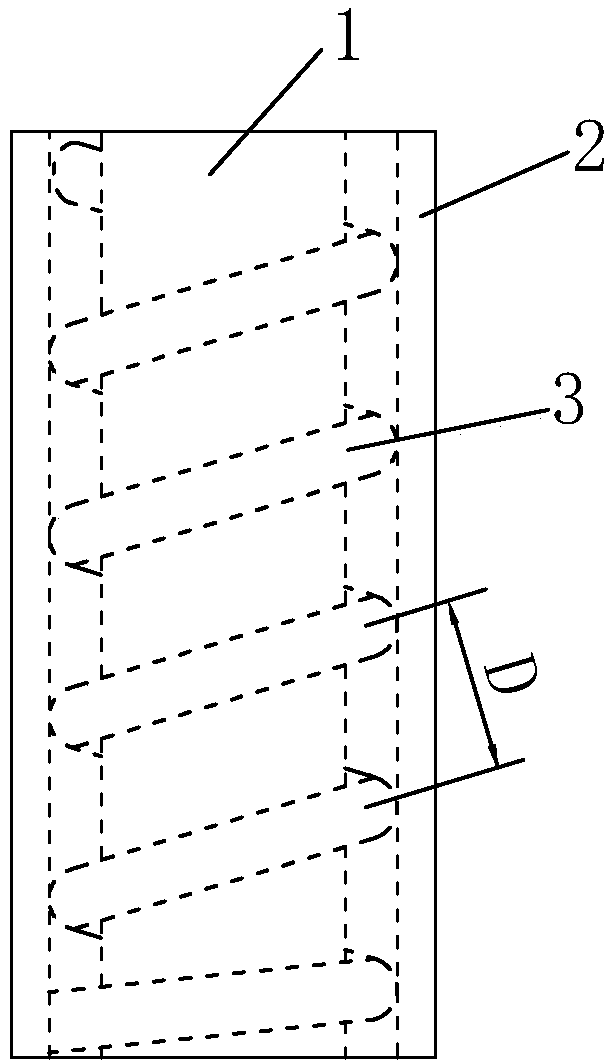
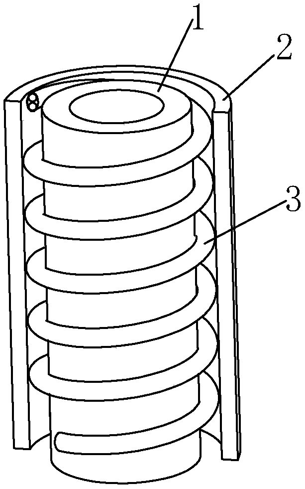
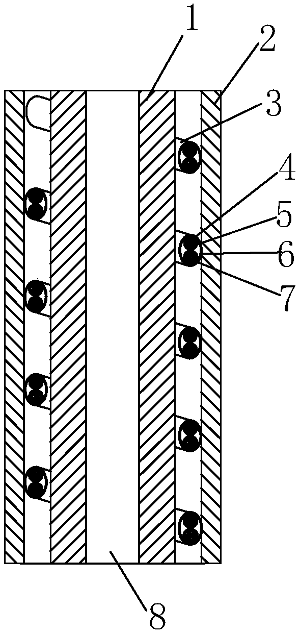
[0015] Such as Figure 1 to Figure 4 As shown, the shock-resistant ventilating or liquid-passing power cord (referred to as "power cord") of the present invention includes a silicone outer tube 2, a silicone ventilating inner tube 1, and a conductive wire 3. The silicone outer tube 2 is a silicone tube with a larger inner hole and a thinner wall thickness. The silicone ventilation inner tube 1 is a silicone tube with a smaller through hole in the middle and a thicker wall thickness. The inner side of the silicone ventilation inner tube 1 is provided with air holes 8. The air tube can be used for ventilation or fluid. The conductive thread 3 is evenly wound on the outer surface of the silicone ventilation inner tube 1 in a helical manner, and the pitch of the conductive thread 3 is 3-10 mm. In this embodiment, the pitch of the conductive thread 3 is 5 mm. figure 1 The distance in D is the pitch. Of course, the pitch of the conductive thread can be any value in the range of 3-1...


PUM


Abstract

The invention provides an anti-shock power line charged with gas or liquid, and relates to a power line. The power line comprises a silica gel outer sleeve, a silica gel gas charging inner pipe, and aconductor wire. The conductor wire is coiled on the outer surface of the silica gel gas charging inner pipe in a spiral manner. The silica gel outer sleeve is sleeved on the outer side of the silicagel gas charging inner pipe which is coiled with the conductor wire, so that the conductor wire is positioned between the inner wall of the silica gel outer sleeve and the outer wall of the silica gelgas charging inner pipe. The conductor wire comprises an anode conductor wire and a cathode conductor wire arranged in parallel. Outer surfaces of the anode conductor wire and the cathode conductor wire are respectively wrapped with inner insulating layers. An outer insulating layer connecting the anode conductor wire and the cathode conductor wire together is arranged out of the inner insulatinglayers of the anode conductor wire and the cathode conductor wire. The anode conductor wire and the cathode conductor wire are respectively formed by braiding a plurality of conductive metal wires and a plurality of bulletproof wires in a mixed manner. The power line has advantages of shock resistance, tensile resistance, stable performance, long service life, and low maintenance cost.

Description

technical field [0001] The invention relates to a power cord, in particular to an anti-shock ventilating or liquid-permeable power cord. Background technique [0002] Existing general power lines usually include a positive lead and a negative lead, which are wrapped by a layer of insulator and arranged side by side, and some power lines will wrap a layer of insulator outside the two leads. This kind of power cord has the following defects: the distance between the positive wire and the negative wire is too close, and when the current suddenly increases, the insulation layer of the wire is easily burned out due to high heat and causes a short circuit. When the short circuit is severe, it is likely to cause a fire. For this reason, the inventor of this patent has invented a kind of anti-short-circuit power cord with ventilation or liquid passage. For its specific structure, please refer to the Chinese utility model patent specification with the patent number ZL201720247207.8. ...

Claims


Application Information

Patent Timeline
IPC IPC(8): H01B7/00H01B7/02H01B7/18H01B9/00F16L11/127F16L11/20
CPCH01B7/0009H01B7/0045H01B7/0072H01B7/0216H01B7/1815H01B7/1825H01B7/189H01B9/006F16L11/127F16L11/20
Inventor 黄广文
Owner 黄广文
Learn More