Method and device for manufacturing fuel cell membrane electrode

A technology of fuel cell membrane and manufacturing method, which is applied to fuel cells, battery electrodes, circuits, etc., can solve problems such as surface A coating damage, and achieve the effects of improving production efficiency and reducing production scrap rates

Pending Publication Date: 2018-08-24
SHENZHEN SHINING AUTOMATION CO LTD
View PDF0 Cites 10 Cited by
  • Summary
  • Abstract
  • Description
  • Claims
  • Application Information

AI Technical Summary

Problems solved by technology

[0004] In order to solve the technical problem that the printing transfer process easily causes damage to the A surface coating in the prior art when the membrane electrode is manufact

Method used


Image

  • Method and device for manufacturing fuel cell membrane electrode
  • Method and device for manufacturing fuel cell membrane electrode
  • Method and device for manufacturing fuel cell membrane electrode

Examples


Example Embodiment

[0036] Example 1

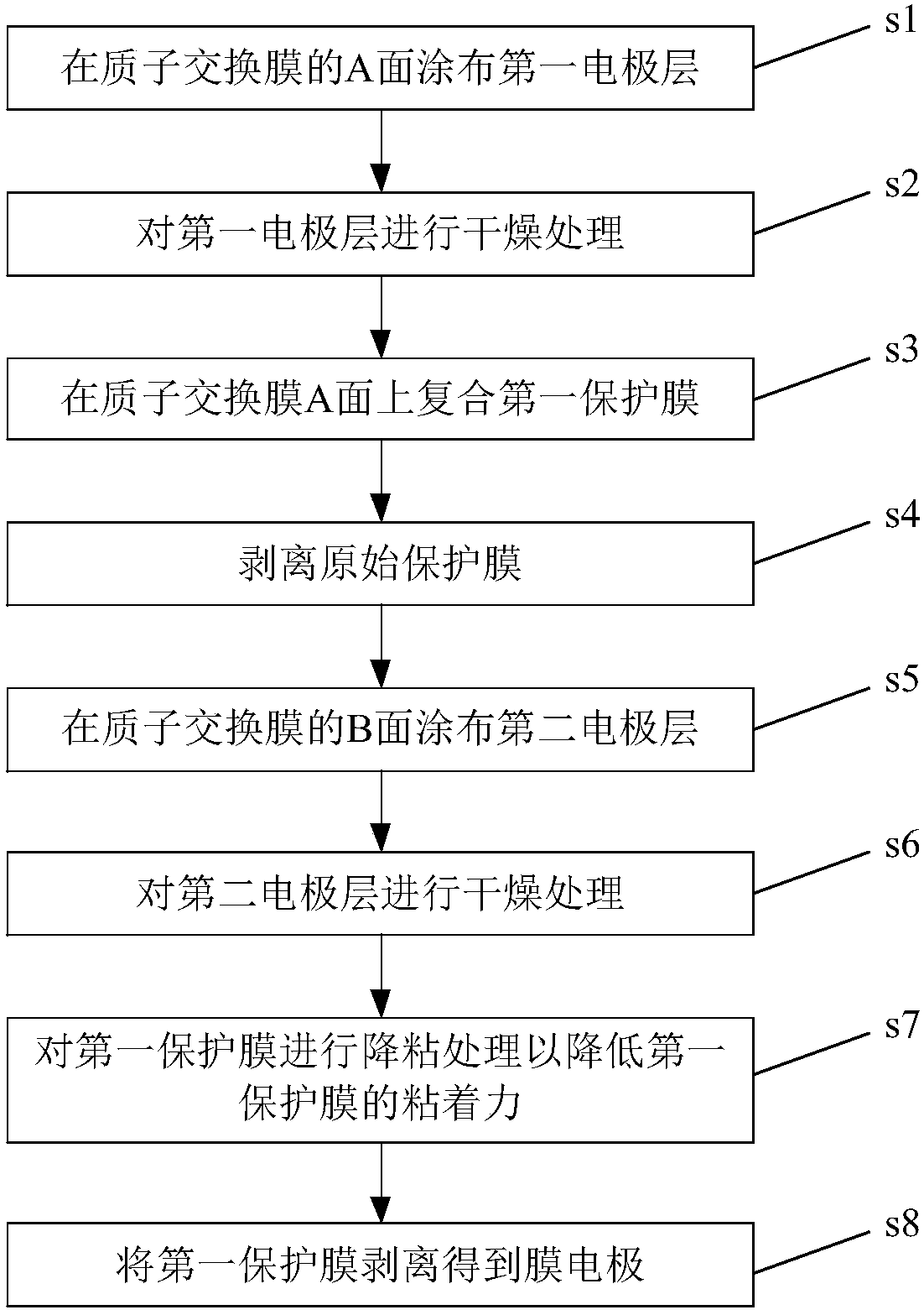
[0037] This embodiment provides a method for manufacturing a fuel cell membrane electrode, and the fuel cell is described by taking a proton exchange membrane fuel cell as an example, as follows figure 1 , including the following steps:

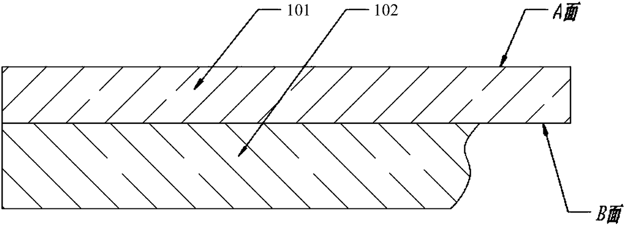
[0038] s1: Coating the first electrode layer on the A side of the proton exchange membrane. like figure 1 As shown, before coating the first electrode layer, the proton exchange membrane is in the original state, with a layer of original protective film 102, the side of the proton exchange membrane 101 that is not protected by the original protective film 102 is called A side, which is protected The surface is called the B surface; in other words, the A surface of the proton exchange membrane 101 before the MEA is not provided with an original protective film, and the B surface is provided with an original protective film 102 . The first electrode layer may be a catalyst anode layer or a catalyst cathode layer, and this ...

Example Embodiment

[0048] Example 2

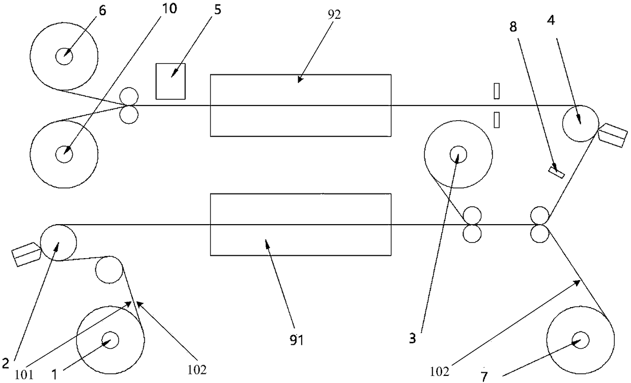
[0049] This embodiment provides a fuel cell membrane electrode manufacturing equipment, such as image 3 ,include:

[0050] The first unwinding device 1 is used to release the proton exchange membrane in the way of unwinding and discharging; the proton exchange membrane is controlled by constant tension to enter the first coating device 2 at a preset speed. like figure 1 As shown, before coating the first electrode layer, the proton exchange membrane is in the original state, with a layer of original protective film 102, the side of the proton exchange membrane 101 that is not protected by the original protective film 102 is called A side, which is protected The side is called the B side.

[0051] The first coating device 2 is arranged on the downstream of the first unwinding device 1, and is used to coat the first electrode layer on the A side of the proton exchange membrane released by the first unwinding device 1; the first electrode layer can be The ...


PUM

PropertyMeasurementUnit
Adhesionaaaaaaaaaa
Adhesionaaaaaaaaaa

Abstract

The invention belongs to the technical field of fuel cells, and discloses a method for manufacturing a fuel cell membrane electrode. The method comprises the following steps: coating the A side of a proton exchange membrane with a first electrode layer, compounding A side of a proton exchange membrane with a first protection membrane, coating the B side of the proton exchange membrane with a second electrode layer, performing viscosity reduction treatment on the first protection membrane, and stripping the first protection membrane to obtain the membrane electrode, wherein the first electrodelayer applied to the A side is protected with the first protection membrane to avoid damages of coating of the second electrode layer to the first electrode layer, the size of the first electrode layer is detected during the coating of the second electrode layer, and the second electrode layer is applied according to the size of the first electrode layer to make the first electrode layer and the second electrode layer aligned in size in order to reduce the production scrap rate. The invention also discloses a manufacturing device. T whole process is completed by using the automatic device without using transferring printing, so the production efficiency is improved.

Description

technical field [0001] The invention belongs to the technical field of fuel cells, and in particular relates to a manufacturing method and equipment for fuel cell membrane electrodes. Background technique [0002] Fuel cells are regarded as the future environmentally friendly new energy because of low pollution or even no pollution. Countries such as Europe, America, and Japan have mastered the development technology of fuel cells and have applied them in production. For example, Ballard of Germany and Toyota of Japan have mass-produced fuel cells. new energy vehicles. The fuel cell membrane electrode (MEA) is composed of a proton exchange membrane and catalyst anodes and catalyst cathodes on both sides. The membrane electrode is the core component of the fuel cell and directly determines the performance of the fuel cell. [0003] like figure 1 As shown, the raw material of the proton exchange membrane has a layer of original protective film 102, the surface of the proton ...

Claims


Application Information

Patent Timeline
IPC IPC(8): H01M8/1004H01M4/88
CPCH01M4/8828H01M8/1004H01M2008/1095Y02P70/50Y02E60/50
Inventor 程俊超关敬党
Owner SHENZHEN SHINING AUTOMATION CO LTD
Why Eureka
Try Eureka