Gap eliminating part

A gap and body technology, applied in the field of gap elimination parts, can solve the problems of different shapes and sizes, weak strength, loose matching structure, etc., to achieve the effect of strong gap elimination ability, lower production cost, and tight fit.

Pending Publication Date: 2018-08-24
SHENZHEN CHOGORI TECH CO LTD
View PDF5 Cites 1 Cited by
  • Summary
  • Abstract
  • Description
  • Claims
  • Application Information

AI Technical Summary

Problems solved by technology

[0002] In the case of power connection or other mechanical connections, the hole-shaft fit is often encountered. In the prior art, an interference fit is usually used to make the hole and the shaft fit tightly. However, there are many defects in the interference fit, such as: 1. The accuracy of the matching holes and shafts is high, otherwise the matching holes and (or) shafts will be excessively deformed or even cracked due to excessive interference, or the matching strength will be weak due to too small interference, thus 2. Even if the hole and shaft fit properly at first, there may be a gap between the hole and shaft during use. Moreover, once the gap is generated, the gap cannot be eliminated, resulting in the easy loosening of the matching structure. For example, in the heat In the case of expansion and contraction, if the holes and shafts are made of materials with different thermal expansion coefficients, gaps are likely to occur; even if the holes and shafts are made of the same material, gaps are likely to occur due to the difference in heat and heat dissipation between the holes and shafts during heating or cooling (especially in electrical connections. Occasionally, the shape and size of the hole axis are different, and the thermal effect generated by the current is different)

Method used


Image

  • Gap eliminating part
  • Gap eliminating part
  • Gap eliminating part

Examples


Embodiment Construction

[0038] The present invention will be described in further detail below in conjunction with accompanying drawing:

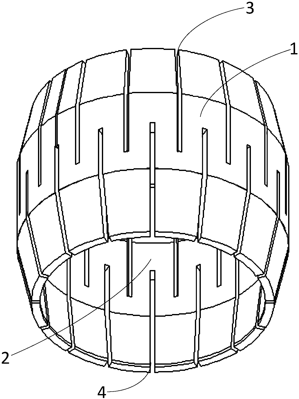
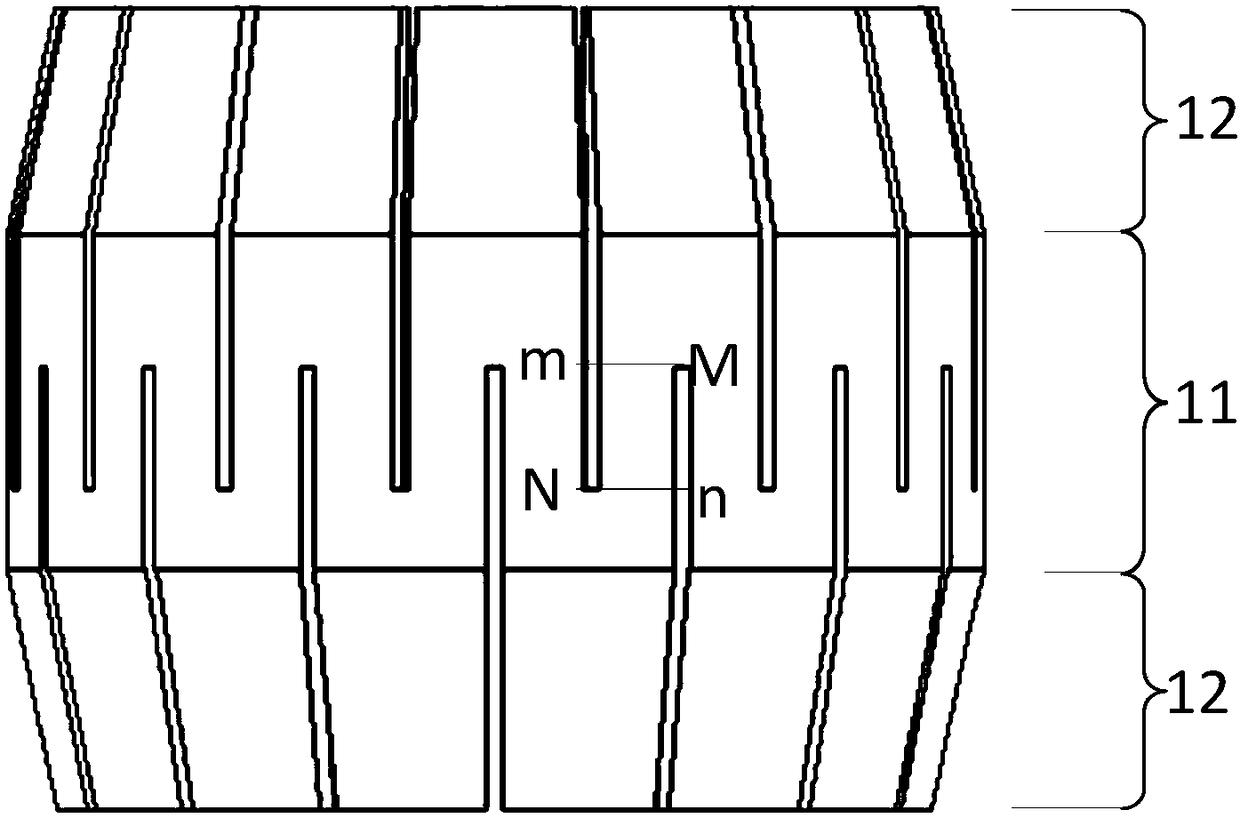
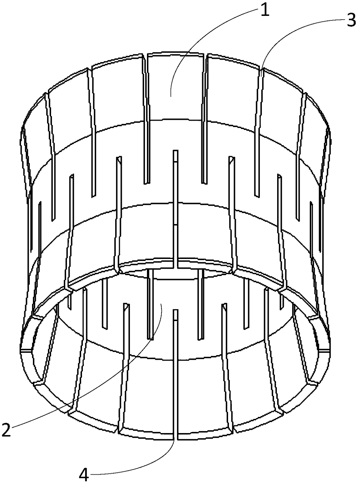
[0039] The gap eliminating part provided by the present invention is made of elastic material, which can be elastic metal material or elastic plastic, etc. In addition, preferably, for the convenience of production, the gap eliminating part is made of the same material as a whole.

[0040] Such as Figure 1 to Figure 5 As shown, the gap eliminating part provided by the present invention is used for tight fitting connection of holes and shafts, and the gap eliminating part includes: a body 1; Through holes 2; the first gap bridging seam 3 and the second gap bridging seam 4 alternately arranged on the side wall of the body 1; wherein, the first gap bridging seam 3 and the second gap bridging seam 4 start from the two ends of the body 1 respectively, And extend along the axial direction; in addition, the first gap bridging seam 3 and the second gap bridging seam 4 d...


PUM


Abstract

The invention is applied to the technical field of connectors and provides a gap eliminating part. The gap eliminating part comprises a first gap bridging seam and a second gap bridging seam which aresequentially and alternatively arranged, wherein the first gap bridging seam and the second gap bridging seam respectively begin from the two ends of the gap eliminating part and are arranged in theaxial direction of the gap eliminating part, the first gap bridging seam and the second gap bridging seam do not penetrate through the gap eliminating part in the axial direction and penetrate througha lateral wall of the gap eliminating part in the radial direction, and in addition, the first gap bridging seam and the second gap bridging seam have lapped parts on the axial direction. The gap eliminating part disclosed by the invention can make hole shafts achieve close fit without the interference fit situation; furthermore, gaps caused by thermal expansion and cold contraction can be made up, and the hole shafts can keep a fastened state all the time.

Description

technical field [0001] The invention relates to the technical field of connectors, in particular to a gap eliminating piece. Background technique [0002] In the case of power connection or other mechanical connections, the hole-shaft fit is often encountered. In the prior art, an interference fit is usually used to make the hole and the shaft fit tightly. However, there are many defects in the interference fit, such as: 1. The accuracy of the matching holes and shafts is high, otherwise the matching holes and (or) shafts will be excessively deformed or even cracked due to excessive interference, or the matching strength will be weak due to too small interference, thus 2. Even if the hole and shaft fit properly at first, there may be a gap between the hole and shaft during use. Moreover, once the gap is generated, the gap cannot be eliminated, resulting in the easy loosening of the matching structure. For example, in the heat In the case of expansion and contraction, if the...

Claims


Application Information

Patent Timeline
Patent Type & Authority Applications(China)
IPC IPC(8): H01R13/15
CPCH01R13/15
Inventor 刘海涛
Owner SHENZHEN CHOGORI TECH CO LTD
Why Eureka
Try Eureka