A current control method for automatically judging the current state of switched reluctance motor

A switched reluctance motor and current state technology, applied in the direction of AC motor control, control system, electrical components, etc., can solve problems such as winding current out of control, overcurrent fault, and controller's failure to discriminate and deal with it in time, so as to prevent overcurrent fault , the effect of uniform heat dissipation effect

Active Publication Date: 2020-12-25
SHANDONG UNIV OF TECH
View PDF5 Cites 0 Cited by
  • Summary
  • Abstract
  • Description
  • Claims
  • Application Information

AI Technical Summary

Problems solved by technology

In actual work, the switched reluctance motor will change from the motoring state to the power generation state, and the controller does not judge and deal with it in time. Because the current chopping method is still in the motoring state, the winding current is out of control, resulting in an overcurrent fault.

Method used


Image

  • A current control method for automatically judging the current state of switched reluctance motor
  • A current control method for automatically judging the current state of switched reluctance motor
  • A current control method for automatically judging the current state of switched reluctance motor

Examples


Embodiment Construction

[0028] In order to make the technical solutions and beneficial effects of the present invention clearer, the implementation manners of the present invention will be further explained in detail below.

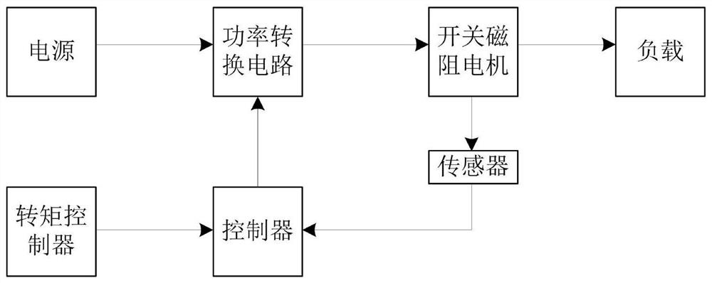
[0029] The invention is used as a control method in the running system of the switched reluctance motor. In the document "Design of 2_2kW Switched Reluctance Motor Drive System", a design principle of the operating system of a switched reluctance motor is recorded. Such as figure 1As shown, a complete operating system of the switched reluctance motor in the prior art includes a controller, a power conversion circuit, a sensor and a switched reluctance motor, and a load linked mechanically with the switched reluctance motor, and a power switch circuit connected External power supply, and torque controller connected to the controller. Inside the system, the controller is electrically connected to the power conversion circuit and the sensor, and the power conversion circuit is el...


PUM


Abstract

The invention discloses a current control method for automatically judging the current state of a switch reluctance motor. The method comprises the following steps: judging whether the reluctance motor is in an electric state or a generating state by judging the relation between the actual current of a phase coil winding and upper and lower given currents; then controlling the on / off of switch tubes inside a power switching circuit according to the result of the judgment, alternately turning off a single switch tube to limit current when the reluctance motor is in the electric operation state,and turning off two switch tubes when the reluctance motor is in the generating state to feed back energy to a bus capacitor, so that overcurrent faults caused by the fact that the off of the switchtubes is not controlled in time are avoided. The judgments for the electric and generating states depend on current signals, and external signals are not needed, so that the circuit structure is simplified, and the operation efficiency is improved.

Description

technical field [0001] The invention relates to the field of motor control, in particular to a current control method for automatically judging the current state of a switched reluctance motor. Background technique [0002] The switched reluctance motor has a simple structure and a large starting torque, and is widely used in presses and other fields. The torque of the switched reluctance motor is realized by controlling the current of the winding, and the control of the winding current is realized by controlling the opening and closing of the switching element connected to the winding. The current control method can be PWM voltage chopping control or current feedback control. Commonly used switched reluctance motors have two switching devices per phase winding. When the two switches are closed at the same time, a positive voltage is applied to both ends of the winding, and electric energy flows from the power supply to the motor; when both switches are turned off, a negati...

Claims


Application Information

Patent Timeline
Patent Type & Authority Patents(China)
IPC IPC(8): H02P25/092
CPCH02P25/092
Inventor 边敦新熊立新马宏昌姜殿波谭培红葛海燕王新维
Owner SHANDONG UNIV OF TECH
Why Eureka
Try Eureka