Supercharge Your Innovation With Domain-Expert AI Agents!

Novel planar marking material carrying tray structure and application thereof

A new type of disk-carrying technology, applied in welding equipment, laser welding equipment, metal processing equipment, etc., can solve the problems of complex transmission mechanism, affecting the moving speed of the transmission mechanism, and damage to the mechanical structure.

Pending Publication Date: 2018-08-28
GUANGZHOU NEW CKLASER CO LTD
View PDF12 Cites 0 Cited by
  • Summary
  • Abstract
  • Description
  • Claims
  • Application Information

AI Technical Summary

Problems solved by technology

For example, Chinese patent CN 202656617U discloses an automatic laser marking machine. The marking material is placed on the transmission mechanism, and then the marking material is moved through the transmission rod. Although such a structure has a certain degree of automation, the speed of the transmission mechanism Slow, can not adapt to a variety of job requirements, especially when the marking material is paper, because the paper is thin, the paper needs to be moved quickly to avoid defective or defective products. At the same time, the laser has a certain range limitation. If the moving speed of the paper is too slow, it will not only affect the marking effect, but also affect the marking accuracy. In other existing marking equipment, the transmission mechanism is very complicated because of the heavy structure of the carrier plate, which affects the movement of the transmission mechanism. In addition, if the carrier moves too fast, the waste generated is not conducive to collection, and the scattered waste not only pollutes the environment, but also may cause damage to the mechanical structure

Method used


Image

  • Novel planar marking material carrying tray structure and application thereof
  • Novel planar marking material carrying tray structure and application thereof
  • Novel planar marking material carrying tray structure and application thereof

Examples


Embodiment

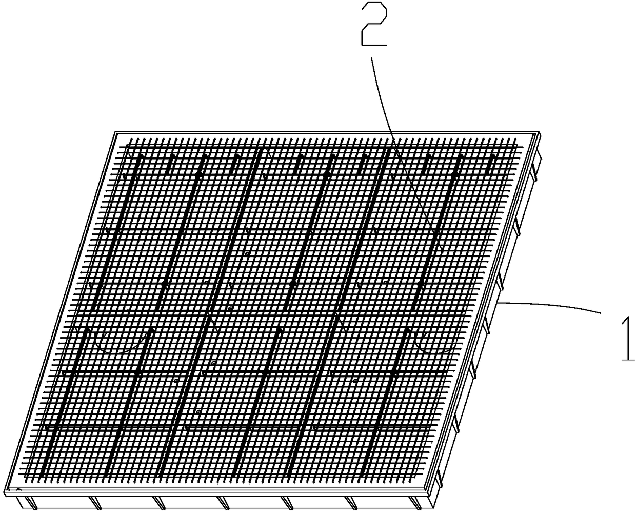
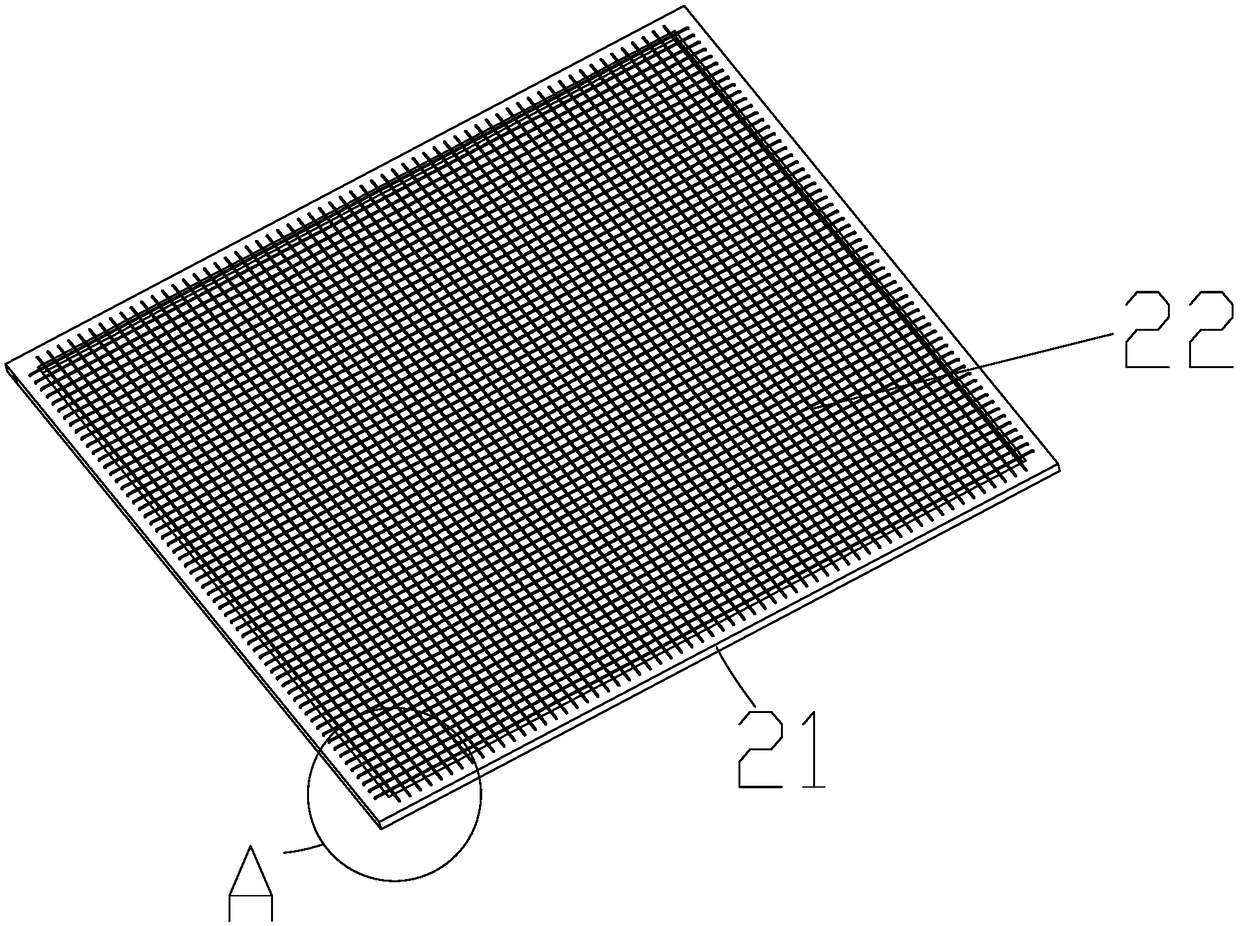
[0037] Such as Figures 1 to 8 As shown, this embodiment provides a novel carrier structure for planar marking materials, including a plastic chassis 1, and the plastic chassis 1 is provided with a placement tray 2 covering the upper surface of the plastic chassis 1, and the placement tray 2 includes a wire frame 21 and a carrying wire 22, the wire frame 21 is fixedly arranged on the plastic chassis 1, and a plurality of the carrying wires 2 are equidistantly arranged on one side of the wire frame 21 in the form of a mesh. On the side surface, one end of the plastic chassis 1 is open, and the opening is connected to the placement tray 2 , and the peripheral edge of the opening extends upwards to form a surrounding groove 11 wrapping the outer edge of the wire frame 21 .

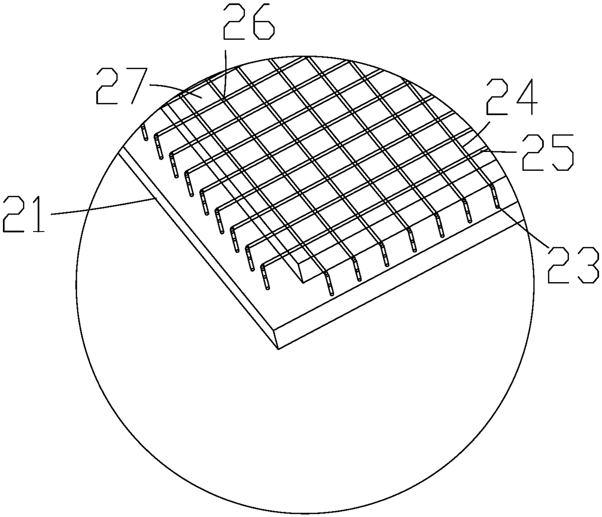
[0038] The wire frame 21 is a regular quadrilateral, and the wire frame 21 is provided with a wire hole 23 corresponding to the position of the carrying wire 22. above the wireframe 21.

[0039] Both ends o...


PUM

PropertyMeasurementUnit
Diameteraaaaaaaaaa

Abstract

The invention provides a novel planar marking material carrying tray structure. The novel planar marking material carrying tray structure comprises a plastic base tray. A carrying tray covering the upper surface of the plastic base tray is arranged on the plastic base tray. The carrying tray comprises a wire frame and carrying wires. The wire frame is fixedly arranged on the plastic base tray. Themultiple carrying wires are equidistantly arranged on the surface of one side of the wire frame in a netted form. One end of the plastic base tray is provided with an opening. The opening is connected with the carrying tray. The peripheral edge of the opening extends upwards to form a surrounding groove wrapping the edge of the outer end of the wire frame. Accordingly, the problems that a commoncarrying tray cannot be matched with a linear motor, and the moving speed is too low are solved.

Description

technical field [0001] The invention relates to the technical field of laser marking equipment, in particular to a novel carrier structure of a plane marking material and its application. Background technique [0002] Laser marking equipment uses laser beams to mark permanent marks on the surface of various substances, and uses laser beams to evaporate surface substances to expose deep substances, or cause chemical and physical changes in surface substances to engrave traces, or pass light energy Burn off part of the material to reveal the graphics and text to be etched. For example, Chinese patent CN 202656617U discloses an automatic laser marking machine. The marking material is placed on the transmission mechanism, and then the marking material is moved through the transmission rod. Although such a structure has a certain degree of automation, the speed of the transmission mechanism Slow, can not adapt to a variety of job requirements, especially when the marking materia...

Claims


Application Information

Patent Timeline
IPC IPC(8): B23K26/70B23K26/142B23K26/362
CPCB23K26/142B23K26/361B23K26/702
Inventor 徐强
Owner GUANGZHOU NEW CKLASER CO LTD
Features
  • R&D
  • Intellectual Property
  • Life Sciences
  • Materials
  • Tech Scout
  • Unparalleled Data Quality
  • Higher Quality Content
  • 60% Fewer Hallucinations
Learn More