Anti-dazzle device and control method thereof, vehicle

An anti-dazzle, rear vehicle technology, applied in the field of vehicle safety, can solve the problems of driver dazzle, increased braking distance, affecting the driver's line of sight, etc., to reduce light intensity, improve safety, and avoid the effect of impact

Inactive Publication Date: 2018-08-28
BOE TECH GRP CO LTD
View PDF7 Cites 6 Cited by
  • Summary
  • Abstract
  • Description
  • Claims
  • Application Information

AI Technical Summary

Problems solved by technology

During this time of about 2 seconds, the driver seems to be driving with his eyes closed, and his ability to observe the surrounding environment is greatly reduced, which is not conducive to the driver's safe driving.
In addition, when the vehicle is driving at night, the light of the high beam of the rear vehicle will shine on the rearview mirr

Method used


Image

  • Anti-dazzle device and control method thereof, vehicle
  • Anti-dazzle device and control method thereof, vehicle
  • Anti-dazzle device and control method thereof, vehicle

Examples


no. 1 example

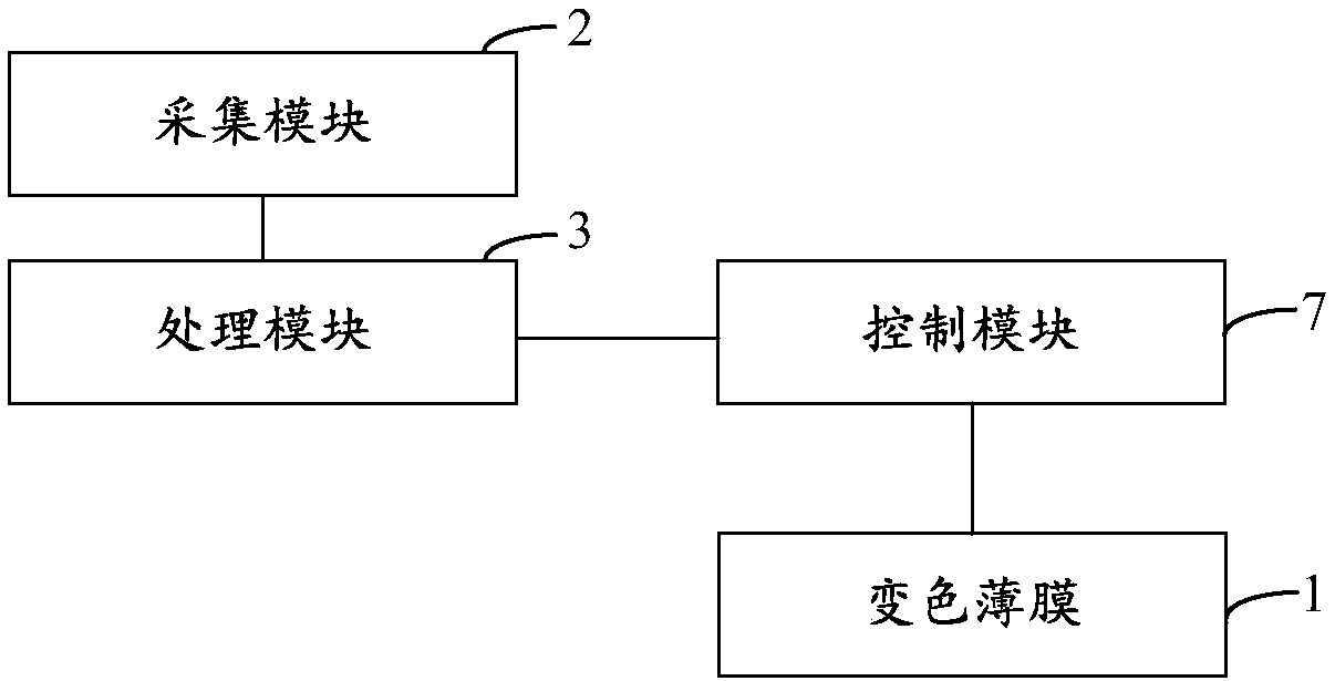
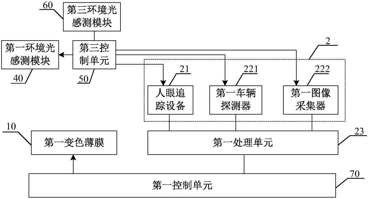
[0047] figure 2 It is a schematic structural diagram of the anti-glare device according to the first embodiment of the present invention. The anti-glare device of this embodiment is mainly used to prevent the driver from being dazzled by the high beam of the vehicle ahead. From figure 2 As can be seen from the figure, in this embodiment, the color-changing film 1 includes a first color-changing film 10, the processing module 3 includes a first processing unit 23, and the control module 7 includes a first control unit 70, and the first control unit 70 is connected to the first control unit 70 respectively. The color-changing film 10 is connected to the first processing unit 23 . Wherein, the first color-changing film 10 is arranged on the front windshield; the first processing unit 20 is used to determine the first glare area on the front windshield according to the information of the pupil of the human eye and the information of the high beam of the vehicle ahead; A contr...

no. 2 example

[0063] Figure 6 It is a schematic structural diagram of the anti-glare device according to the second embodiment of the present invention. The anti-dazzling device of this embodiment is used to simultaneously prevent the driver from being dazzled by the high beam lights of the front vehicle and the high beam lights of the rear vehicle. From Figure 6 As can be seen from the figure, the anti-glare device is based on the first embodiment, the color-changing film 1 also includes a second color-changing film 110, the processing module 3 also includes a second processing unit 123, and the control module 7 also includes a second control unit 170. The second color-changing film 110 is arranged on the rearview mirror, and the second processing unit 123 is used to determine the second glare area on the rearview mirror according to the information of human eyes and the information of the high beam of the vehicle behind, and the second control unit 170 respectively Electrically conne...

no. 3 example

[0080] The anti-glare device of this embodiment is based on the second embodiment, wherein the color-changing film further includes a third color-changing film, the processing module further includes a third processing unit, and the control module further includes a third control unit. The third color-changing film is arranged on the rear windshield. The third processing unit is used to determine the third dazzling area on the rear windshield according to the information of human eyes and the information of the high beam of the vehicle behind. The third control unit is configured to control the third color-changing film according to the third glare area to reduce the light transmittance of the third glare area.

[0081] Figure 10 A schematic diagram of the principle of obtaining the third dazzling area is shown. In the second embodiment, the second dazzle area D on the interior rearview mirror is determined, and the position of the rear windshield 400 in the vehicle is dete...


PUM


Abstract

The invention discloses an anti-dazzle device, a control method thereof and a vehicle thereof. The anti-dazzle device comprises a discoloration thin film, an acquisition module, a processing module and a control module, wherein the discoloration thin film is arranged on the light path between high beams outside the vehicle and human eyes; the acquisition module is used for acquiring information about the pupils of the human eyes and information about the external high beams; the processing module is used for determining a dazzling area on the discoloration thin film; the control module is usedfor reducing the intensity of light entering the human eyes through the dazzling area by controlling the discoloration thin film according to the dazzling area. The anti-dazzle device has the advantages of avoiding the impact of vehicles' external high beams on a driver, prevent the driver from dazzling, and improving the safety of night driving. Further provided is the control method of the anti-dazzle device and the vehicle of the anti-dazzle device.

Description

technical field [0001] The invention relates to the technical field of vehicle safety, in particular to an anti-glare device, a control method thereof, and a vehicle. Background technique [0002] When a vehicle is driving at night, it usually uses high beams to see the road ahead. When meeting cars, the high beams of the oncoming vehicle will greatly stimulate the eyes of the driver, causing the driver to be instantly dazzled. Depending on the driver's own vision and the surrounding environment, the duration of the glare is also different, but the duration of the glare is at least about 2 seconds. During this time of about 2 seconds, the driver is driving with his eyes closed, and his ability to observe the surrounding environment is greatly reduced, which is not conducive to the driver's safe driving. In addition, when the vehicle is driving at night, the light of the high beam of the rear vehicle will shine on the rearview mirror inside and outside the car, and the stro...

Claims


Application Information

Patent Timeline
IPC IPC(8): B60J3/04G02F1/163G02F1/153
CPCG02F1/153G02F1/163B60J3/04G02F1/1313G02F1/133502G02F1/155G02F1/157
Inventor 魏伟
Owner BOE TECH GRP CO LTD
Why Eureka
Try Eureka