A cleaning mechanism for electroplating tank

A technology for cleaning mechanism and electroplating tank, which is applied to electrolytic components, electrolytic process, cells, etc., can solve the problem of not being able to clean the bottom surface and side wall of the electroplating tank at the same time, and achieve the effect of being convenient for storage and placement.

Active Publication Date: 2019-10-18
新沂市恒利玻璃有限公司
View PDF4 Cites 0 Cited by
  • Summary
  • Abstract
  • Description
  • Claims
  • Application Information

AI Technical Summary

Problems solved by technology

[0004] For this reason, the technical problem to be solved by the present invention is that the cleaning mechanism used for the electroplating tank in the prior art cannot satisfy the simultaneous cleaning of the bottom surface and the side wall of the inside of the electroplating tank, thereby proposing a cleaning mechanism for the electroplating tank

Method used


Image

  • A cleaning mechanism for electroplating tank
  • A cleaning mechanism for electroplating tank
  • A cleaning mechanism for electroplating tank

Examples


Embodiment Construction

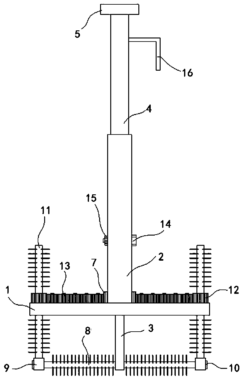
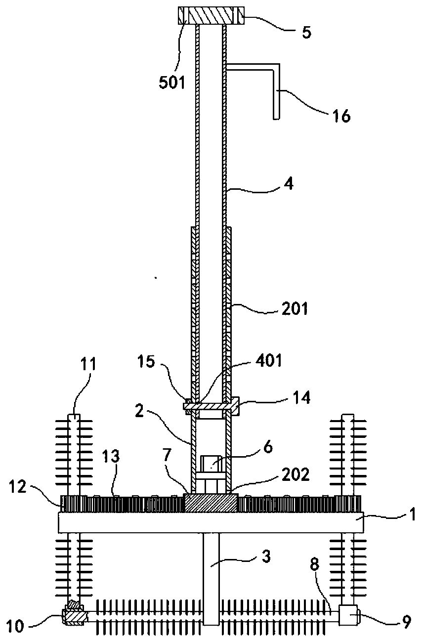
[0022] Such as figure 1 , figure 2 , image 3 Shown, a kind of cleaning mechanism for electroplating tank of the present invention comprises:

[0023] Horizontal pole 1, above the middle part of the pole 1 is formed with a vertical first connecting rod 2, and below the middle part of the pole 1 is formed with a vertical second connecting rod 3, the first connecting rod 2 is plugged with a vertical support rod 4, the upper end of the support rod 4 is formed with a horizontal mounting plate 5, the lower end of the first connecting rod 2 is provided with a rotating motor 6, and the output of the rotating motor 6 The shaft is connected with driving gear 7. A plurality of first positioning holes 201 are formed on the opposite side walls of the first connecting rod 2, and second positioning holes 401 are formed on the two opposite side walls of the lower end of the support rod 4, through which the positioning bolts 14 pass. A positioning nut 15 is screwed behind the second posi...


PUM


Abstract

The invention discloses a cleaning mechanism for a plating bath. The cleaning mechanism comprises a fulcrum bar, a first connecting rod, a second connecting rod, a supporting rod, a mounting plate, arotary motor, a driving gear, a first brush roll, a connecting block, a baffle, second brush rolls, a driven gear, an idle gear, positioning boltss, a positioning nut and a hook. The horizontal firstbrush roll is arranged at the lower end of the fulcrum bar, and the vertical second brush rolls are arranged at the two ends of the fulcrum bar, so that the inner side bottom surface and the side wallof the plating bath can be convenient cleaned at the same time. The leaning mechanism can drives the driving gear and the driven gear to be operated by being provided with the rotary motor, thereby realizing the automatic rotation of the second brush rolls; the cleaning mechanism can convenient adjust the depth of the supporting in the first connecting rod by being provided with the a positioninghole in the first connecting rod, being provided with a second positioning hole in the supporting rod and performing fixing through the positioning bolts, thereby realizing height adjustment of the cleaning mechanism.

Description

Technical field: [0001] The invention belongs to the technical field of electroplating equipment, and in particular relates to a cleaning mechanism for an electroplating tank. Background technique: [0002] Electroplating is the process of plating a thin layer of other metals or alloys on the surface of certain metals using the principle of electrolysis. It is a process of using electrolysis to attach a layer of metal film to the surface of metal or other material parts to prevent metal oxidation ( Such as rust), improve wear resistance, electrical conductivity, reflective properties, corrosion resistance (copper sulfate, etc.) and enhance the appearance. [0003] And electroplating is realized in the electroplating tank, the electroplating solution is corrosive to the electroplating tank, and will produce phenomena such as fouling in the electroplating tank, so the electroplating tank needs to be cleaned regularly, and the existing cleaning is generally manual cleaning, whi...

Claims


Application Information

Patent Timeline
Patent Type & Authority Patents(China)
IPC IPC(8): C25D21/08
Inventor 徐亚维
Owner 新沂市恒利玻璃有限公司
Why Eureka
Try Eureka