Flotation concentrate pulp delivery pump tank assembly

A technology for flotation concentrate and conveying pump, which is applied to pump elements, variable displacement pump parts, parts of pumping devices for elastic fluids, etc. The effect of the probability of a large spill

Pending Publication Date: 2018-08-28
CHINA ENFI ENGINEERING CORPORATION
View PDF0 Cites 2 Cited by
  • Summary
  • Abstract
  • Description
  • Claims
  • Application Information

AI Technical Summary

Problems solved by technology

[0002] In the related technology, the conventional concentrate foam pump pool of the flotation plant of the mine concentrator often has the phenomenon of "sinking", especially in the process flow where the flotation concentrate foam is relatively viscous, du

Method used


Image

  • Flotation concentrate pulp delivery pump tank assembly
  • Flotation concentrate pulp delivery pump tank assembly
  • Flotation concentrate pulp delivery pump tank assembly

Examples


Embodiment 1

[0063] The technical scheme is suitable for the situation that the slurry in the flotation concentrate has little foam or little viscosity.

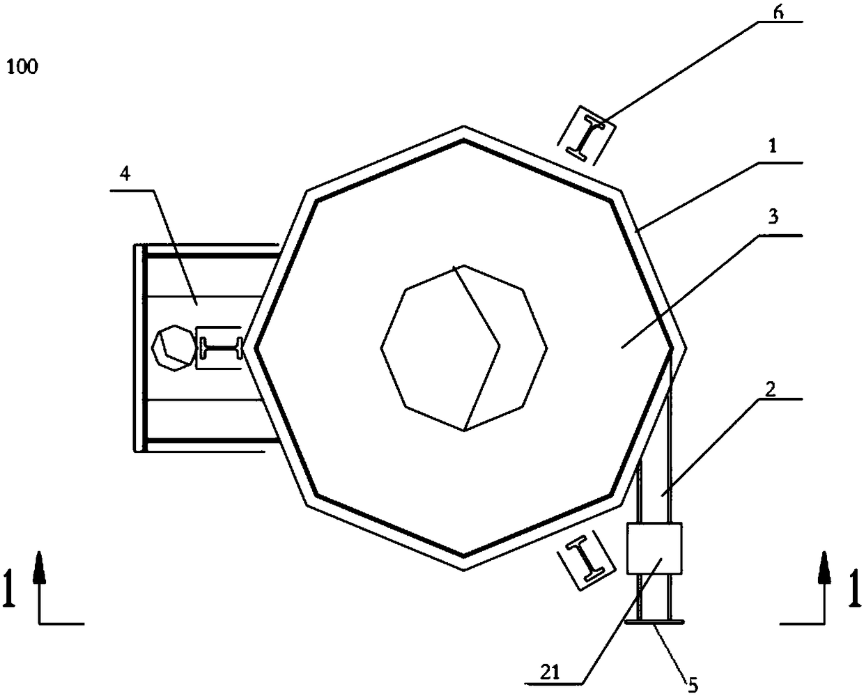
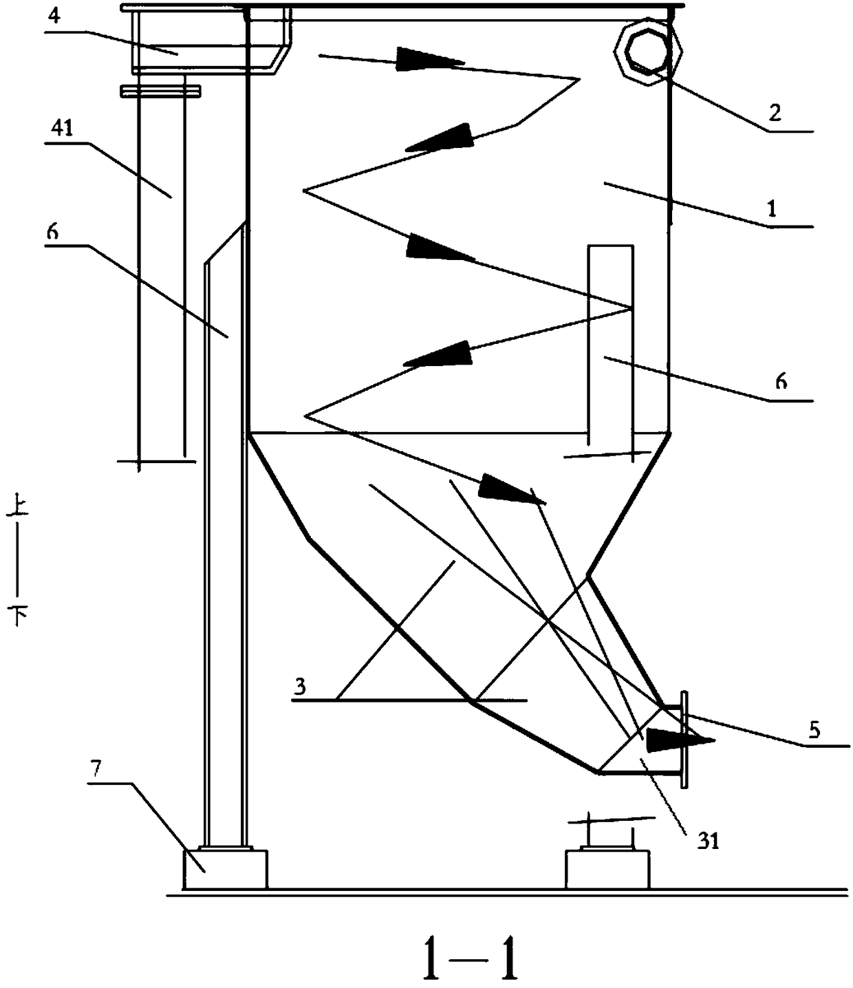
[0064] The flotation concentrate ore slurry delivery pump pool assembly 100 includes a pump pool body 1, the pump pool body is mainly a cylindrical body, and the upper part of the cylindrical body is provided with a slurry overflow collection device 4 and a horizontally arranged feeding pipe 2 for feeding The feed pipe 2 is arranged horizontally and tangentially along the cylindrical shell. The ore feeding method adopts self-flow feeding, and the ore slurry is fed in horizontally along the cylinder body by gravity, and the initial velocity entering the pump pool body 1 is relatively small, and the feeding point is tangent to the pump pool body wall and is subjected to the action of the pump pool body wall. Smooth, so there will be no secondary generation of pulp foam that affects the transportation. The lower part of the pump pool body ...

Embodiment 2

[0066] The technical scheme is suitable for the situation that there are many slurry foams and high viscosity in the flotation concentrate.

[0067] According to the embodiment of the present invention, the pump pool assembly 100 for flotation concentrate slurry delivery includes a pump pool body 1, the pump pool body 1 is mainly a cylindrical cylinder, and the upper part of the cylindrical cylinder is provided with a slurry overflow collection device 4 and a horizontal arrangement The feeding pipe 2 is provided horizontally and tangentially along the cylindrical shell. The ore feeding method is to use pressure feeding, that is, the ore feeding pipe 2 is equipped with a booster device 21 or the height difference configuration of the ore feeding is increased, so that the ore pulp has a suitable initial velocity after entering the cylinder through the feeding pipe 2, and the ore pulp is fed by the upper part. To the lower part, it flows spirally along the wall of the pump pool b...


PUM


Abstract

The invention discloses a flotation concentrate pulp delivery pump tank assembly. The flotation concentrate pulp delivery pump tank assembly comprises a pump tank body, a feed pipe, a variable diameter flow guide device and a slurry pump, wherein the pump tank body is provided with a feed port and a discharge port; the feed pipe is arranged at the feed port to horizontally feed a material into thepump tank body; the variable diameter flow guide device is arranged at the discharge port of the pump tank body; the slurry pump is connected with the variable diameter flow guide device; the variable diameter flow guide device is configured into the shape matched with the shape of the slurry pump so as to guide out flotation concentrate getting into the pump tank body through the feed pipe. According to the flotation concentrate pulp delivery pump tank assembly, the variable diameter flow guide device is configured into the shape matched with the shape of the slurry pump so as to guide out flotation concentrate getting into the pump tank body through the feed pipe better, and the probability that a great deal of concentrate pulp overflows suddenly from the pump tank body can be reduced.

Description

technical field [0001] The invention relates to the technical field of mining machinery, in particular to a flotation concentrate pulp delivery pump pool assembly. Background technique [0002] In the related technology, the conventional concentrate foam pump pool of the flotation plant of the mine concentrator often has the phenomenon of "sinking", especially in the process flow where the flotation concentrate foam is relatively viscous, due to the "spreading" of the viscous foam pulp The "effect" reduces the delivery efficiency of the slurry pump connected to the pump pool, so that the concentrated ore slurry overflows suddenly along the wall of the pump pool due to the inability to pump in time. Contents of the invention [0003] The present invention aims to solve at least one of the technical problems existing in the prior art. For this reason, the present invention proposes a flotation concentrate slurry delivery pump pool assembly, which can reduce the possibility ...

Claims


Application Information

Patent Timeline
IPC IPC(8): F04B15/02F04B53/00
CPCF04B15/02F04B53/00
Inventor 高立强何荣权刘俊唐广群孙明俊杨少燕
Owner CHINA ENFI ENGINEERING CORPORATION
Why Eureka
Try Eureka