Engineering machinery, walking system and control method

A control method and walking system technology, applied in the field of control, can solve problems such as economic loss, low maximum driving torque, and high driving resistance, and achieve the effects of prolonging service life, increasing driving torque, and increasing driving force

Pending Publication Date: 2022-03-22
SUNWARD INTELLIGENT EQUIP
View PDF0 Cites 0 Cited by
  • Summary
  • Abstract
  • Description
  • Claims
  • Application Information

AI Technical Summary

Problems solved by technology

If the driver quickly starts the hydraulic pump to drive the hydraulic motor to rotate, the hydraulic motor needs to drive the relevant mechanical transmission components to drive the excavator with large inertia to start. For the same oil supply flow of the hydraulic pump, the hydraulic motor with small displacement is more likely to cause Hydraulic system produces high pressure shocks
When the driver selects the high-speed walking mode, the initial displacement of the hydraulic motor is in a small displacement state before the excavator starts to walk, so the start of the excavator is more likely to cause high-pressure shocks in the hydraulic system
During the years of work, the excavator will start and walk frequently, and the high-speed walking mode will cause more frequent high-pressure shocks in the hydraulic system, and the hydraulic motor and related components are more likely to be damaged, thereby causing economic losses to the user.
[0004] During the walking process of the excavator, in the high-speed walking mode, the hydraulic motor always has a small displacement, subject to the setting pressure of the relief valve, the maximum driving torque is relatively low, and the driving resistance is greater on muddy roads or during steering. The hydraulic system is more prone to high-pressure overflow, resulting in insufficient driving force of the excavator to continue driving and wasting energy

Method used


Image

  • Engineering machinery, walking system and control method
  • Engineering machinery, walking system and control method
  • Engineering machinery, walking system and control method

Examples


Embodiment Construction

[0048]The following will clearly and completely describe the technical solutions in the embodiments of the present invention with reference to the accompanying drawings in the embodiments of the present invention. Obviously, the described embodiments are only some, not all, embodiments of the present invention. Based on the embodiments of the present invention, all other embodiments obtained by persons of ordinary skill in the art without making creative efforts belong to the protection scope of the present invention.

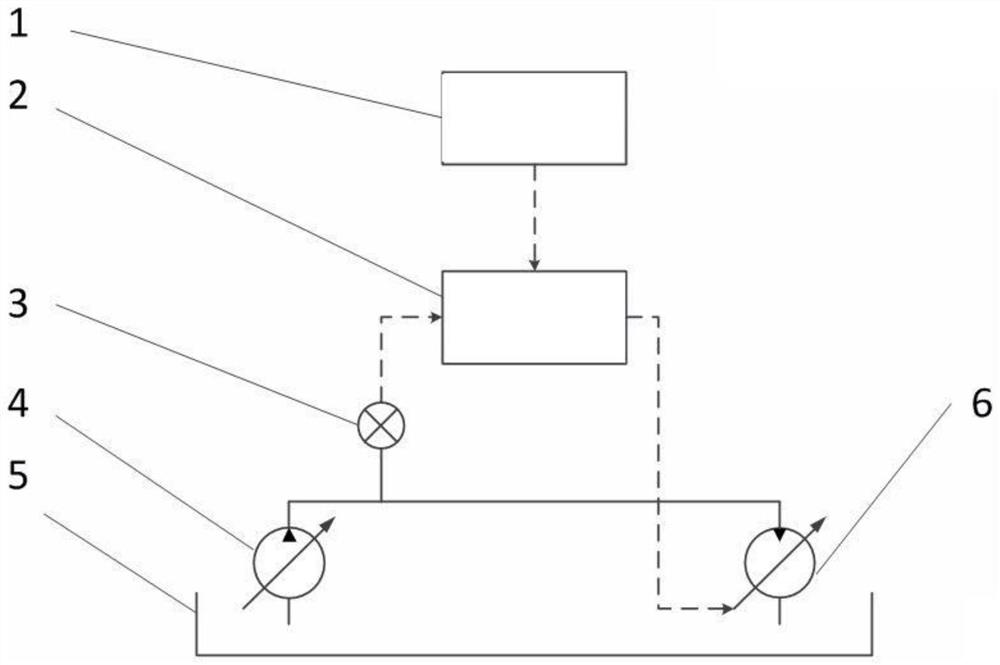
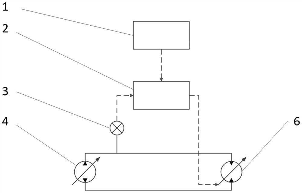
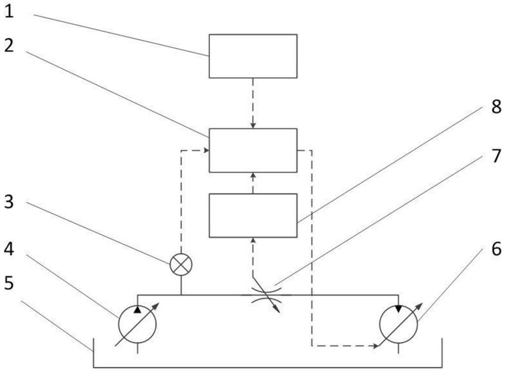
[0049] The core of the present invention is to provide a control method, which can effectively reduce the pressure shock of the hydraulic system during the starting and walking of the construction machinery in the high-speed traveling mode, reduce the pressure shock probability of the construction machinery in the high-speed traveling mode, and extend the life of the hydraulic motor. and the service life of related transmission components; reduce the probability...


PUM


Abstract

The invention discloses an engineering machine, a walking system and a control method, the control method is suitable for the walking system, and the walking system comprises a hydraulic pump and a walking motor; the control method comprises the steps that the input speed and the pressure value of a hydraulic pump outlet or a walking motor inlet are obtained; and adjusting the displacement of the travel motor according to the pressure value and the input speed. According to the control method provided by the invention, high-pressure impact in a starting state or a high-speed walking mode of the engineering machinery can be avoided in the implementation process; the probability that the hydraulic system overflows when the torque is low in the high-speed driving mode is reduced; therefore, the service lives of the hydraulic motor and related transmission parts are prolonged; the probability of overflow of the hydraulic system in the walking process is reduced, and energy is saved; in addition, under specific conditions, the displacement of the hydraulic motor can be actively increased, the driving torque is improved, and the driving force of the whole machine is improved.

Description

technical field [0001] The invention relates to the technical field of engineering machinery, and more specifically, to a control method. In addition, the present invention also relates to a walking system for implementing the above-mentioned control method and a construction machine including the above-mentioned walking system. Background technique [0002] In the walking system of the existing crawler hydraulic excavator, the hydraulic pump and the hydraulic motor are connected through pipelines, and the hydraulic motor drives the mechanical transmission components such as the reducer, the driving wheel, and the crawler belt to move to realize the walking of the excavator. Before walking, the driver selects low-speed driving or high-speed driving mode, and the setting command is sent to the controller, which adjusts the displacement of the hydraulic motor for walking through the electrical system. Low-speed driving corresponds to large displacement of hydraulic motors, and...

Claims


Application Information

Patent Timeline
IPC IPC(8): F15B11/16F15B11/04F15B21/08F15B19/00
CPCF15B11/16F15B11/04F15B21/087F15B19/00
Inventor 邓东朱建新何松泉刘仁辉陈浩文
Owner SUNWARD INTELLIGENT EQUIP
Why Eureka
Try Eureka