Two-phase separation micro-channel heat sink

A micro-channel and phase-separation technology, applied in electrical components, electrical solid devices, circuits, etc., can solve problems such as excessive fluid pressure drop, deterioration of micro-channel heat sink heat dissipation, flow instability, etc., to enhance heat exchange capacity. , Solve the phenomenon of excessive fluid pressure drop and flow instability, and increase the effect of heat exchange area

Active Publication Date: 2018-08-28
TIANJIN JINHANG COMP TECH RES INST
View PDF6 Cites 11 Cited by
  • Summary
  • Abstract
  • Description
  • Claims
  • Application Information

AI Technical Summary

Problems solved by technology

However, when the boiling reaction occurs in the microchannel, the single-phase fluid will form a gas-liquid two-phase fluid, resulting in excessive pressure drop and unstable flow of the fluid in the microchannel, thereby deteriorating the heat dissipation effect of the microchannel heat sink.

Method used


Image

  • Two-phase separation micro-channel heat sink
  • Two-phase separation micro-channel heat sink
  • Two-phase separation micro-channel heat sink

Examples


Embodiment Construction

[0016] Specific embodiments of the present invention are given below. The specific embodiments are only used to further describe the present invention in detail, and do not limit the protection scope of the claims of this application.

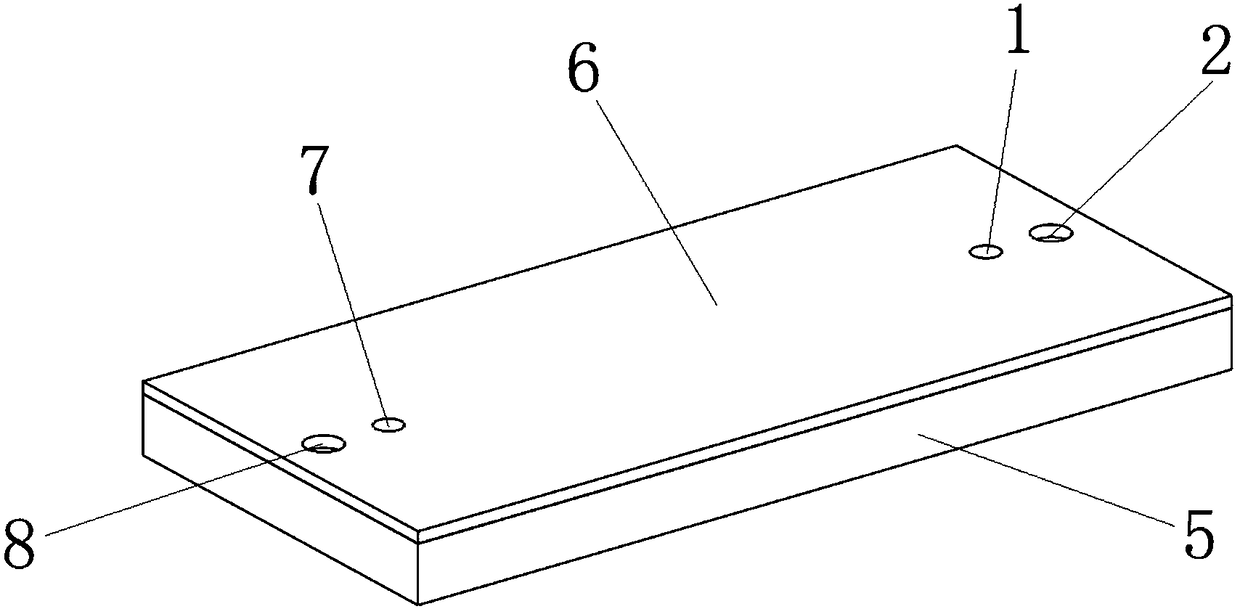
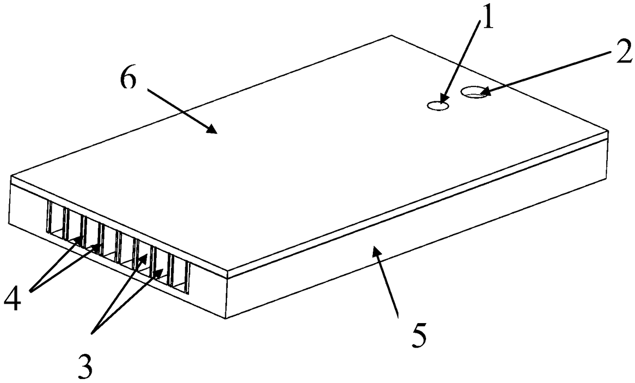
[0017] The invention provides a two-phase separation microchannel heat sink (see Figure 1-4 , Referred to as heat sink), characterized in that the heat sink includes a microchannel array, a bottom plate 5 and a cover plate 6;

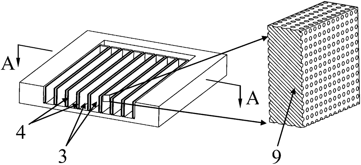
[0018] The bottom plate 5 and the cover plate 6 are connected by bonding to form the main structure of the heat sink; the bottom plate 5 is etched with a microchannel array, which is composed of a gas channel 3 and a liquid channel 4, wherein the gas channel 3 and the liquid channel 4 are staggered, and the side walls of the gas channel and the liquid channel are both multi-through-hole structures 9; the cover plate 6 has a gas inlet 1, a liquid inlet 2, a gas outlet 7 and a liquid outlet 8;

[0019] The gas channel 3 has a ...


PUM


Abstract

The invention discloses a two-phase separation micro-channel heat sink. The heat sink comprises a microchannel array, a bottom plate and a cover plate. The bottom plate and the cover plate are connected through a boding mode to form a main body structure of the heat sink. The microchannel array is etched on the bottom plate. The microchannel array is formed by gas channels and liquid channels, wherein the gas channels and the liquid channels are arranged alternately, and the side walls of the gas channels and the liquid channels are respectively in a multi-through-hole structure. The heat sinkadopts the two-phase separation transmission channels, which are formed by the gas channels and the liquid channels; and the gas channels and the liquid channels realize separate transmission to allow working liquid and gas to be transmitted separately, thereby enhancing phase change process of fluid in the micro-channel heat sink, solving the problems of too large fluid pressure drop and flow instability in the liquid channels and enhancing heat exchange capability.

Description

Technical field [0001] The invention relates to the field of high heat flux density electronic equipment, in particular to a two-phase separation microchannel heat sink for high heat flux density electronic devices. Background technique [0002] With the rapid development of the microelectronics industry, the feature size of transistors has been continuously reduced, and the degree of integration has been greatly improved. The heat flux density per unit area of ​​electronic chips has also been continuously increased. The heat density of high-speed electronic devices has reached 5-10MW / m 2 , Heat dissipation has become the main "bottleneck" of its development. [0003] Micro-channel heat sinks have been widely studied and applied in the thermal management of electronic devices with the advantages of high heat dissipation efficiency, small size, low thermal resistance, and low flow. Generally, the microchannel structure in the microchannel heat sink has only liquid channels, and the ...

Claims


Application Information

Patent Timeline
Patent Type & Authority Applications(China)
IPC IPC(8): H01L23/367H01L23/467H01L23/473
CPCH01L23/367H01L23/467H01L23/473
Inventor 李岩王可刘慧婕赵斌
Owner TIANJIN JINHANG COMP TECH RES INST
Why Eureka
Try Eureka